
HART is a communication protocol used in plant automation and it is the best overall solution for obtaining value-added device and diagnostic information in digital form while retaining compatibility with legacy 4-20 mA automation architectures.
The HART ("Highway Addressable Remote Transducer") protocol was developed by Rosemount Inc., based on the Bell 202 telephone communications standard in the mid-1980s as a proprietary digital communication protocol for their smart field instruments. Soon it evolved into HART and in 1986 it was made an open protocol so other companies could use it and even more users could benefit.
The protocol operates by using the frequency shift keying (FSK) principle. The digital signal is made up of two frequencies 1,200 Hz and 2,200 Hz representing bits 1 and 0, respectively.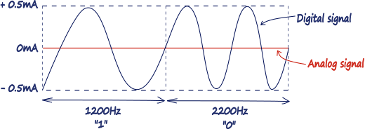
Figure 1. HART Frequency Shift Keying.
Sine waves of these two frequencies are superimposed on the direct current (DC) analog signal cables to provide simultaneous analog and digital communications. The digital information is carried by a low-level modulation. Because the average value of the FSK signal is always zero, the 4–20 mA analog signal is not affected. The digital communication signal has a response time of approximately 2–3 data updates per second without interrupting the analog signal. A minimum loop impedance of 230 ohm is required for communication.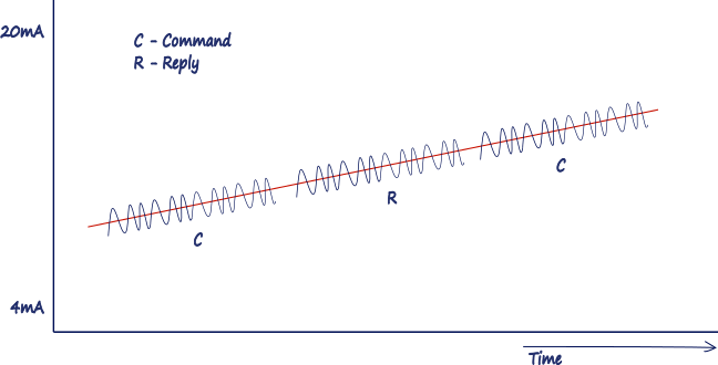 Figure 2. HART over 4..20mA signal.
Combining analog and digital communication the HART protocol may be called “hybrid”. The digital signal does not affect the analog reading because it's removed from the analog signal by standard filtering techniques. The ability to carry this added digital information is the basis for HART's key benefits.
In general, the installation practice for HART communicating devices is the same as conventional 4-20mA instrumentation. Individually shielded twisted pair cable, either in single-pair or multi-pair varieties, is the recommended wiring practice. Unshielded cables may be used for short distances if ambient noise and cross-talk will not affect communication.
Analog signal, information is sent only one way (Input or Output). Digital information, on the other hand, can travel in both directions using the HART digital communications signal. In this way instrument that traditionally only sends the measured process value can provide additional information like:
- Device Status & Diagnostic Alerts.
- Process Variables & Units.
- Loop Current & % Range.
- Basic Configuration Parameters.
- Manufacturer
- Device Tag
HART devices that are digitally polled by a host can provide data telling if they're correctly configured and operating correctly. This eliminates the need for most routine checks and helps detect failure conditions before they cause a major process problem.
HART is also vendor independent, there's no danger of getting locked into limited vendor-specific or regional "standards", it isn't owned by an individual company, nor regulated by a single nation or standards body. Instead, the technology is managed by the independent, not for- profit HART Communications Foundation.
Network configuration modes
HART devices can operate in one of two network configurations: point-to-point or multidrop.
In point-to-point mode, the traditional 4–20 mA signal is used to communicate one process variable, while additional process variables, configuration parameters, and other device data are transferred digitally using the HART protocol. The 4–20 mA analog signal is not affected by the HART signal and can be used in the normal way. The HART communication digital signal gives access to secondary variables and other data that can be used for operations, commissioning, maintenance, and diagnostic purposes.
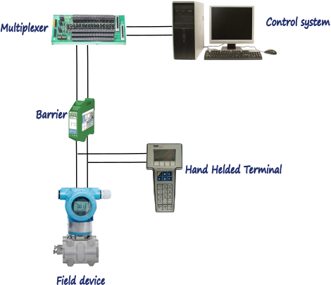
Figure 3. HART point-to-point operating mode.
The multidrop mode of operation requires only a single pair of wires and, if applicable, safety barriers and an auxiliary power supply for up to 15 field devices (Figure 3). All process values are transmitted digitally. In multidrop mode, all field device polling addresses are >0, and the current through each device is fixed to a minimum value (typically 4 mA).
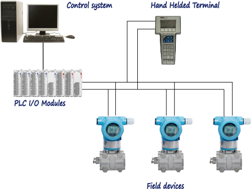
Figure 3. HART mutlidrop operating mode.
The analog loop current does not change in relation to the process and thus does not reflect the primary variable. Communications in multidrop mode are entirely
digital. The typical multidrop network enables two-wire measurement devices to be connected in parallel. Two-wire loop-powered and four-wire active-source devices can be connected in the same network. If both two and four-wire devices are used in the same network, three wires must be used to properly connect the devices
Multi-drop topologies are not as common as point-to-point, but it has been gaining some popularity in certain applications. The two issues that multi-dropping HART has are:
- Update rate is very slow.
- Network have to be carefully designed.
When HART devices are multi-dropped, the analog channel can no longer be used for the Process Variable, so the digital channel has to be used. If you multi-drop two devices, your update rate will be once per second. As the number increases, update rate increases. This is not acceptable in many applications but in some non-time critical applications can be useful.
Types of Data Transaction
HART is a master-slave communication protocol, which means that during normal operation, each slave (field device) communication is initiated by a master. There can be two masters (primary and secondary) to communicate with slave devices and provide additional operational flexibility. The two masters can connect to each HART loop. The primary master is generally a distributed control system (DCS), programmable logic controller (PLC), or a personal computer (PC). The secondary master can be a handheld terminal or another PC. Slave devices are transmitters, actuators, controllers that respond to commands from the primary or secondary master.
Some HART devices support the optional burst communication mode. Burst mode enables faster communication (3–4 data updates per second). In burst mode, the master instructs the slave device to continuously broadcast a standard HART reply message (e.g., the value of the process variable). The master receives the message at the higher rate until it instructs the slave to stop bursting.
HART command set
The HART command set provides uniform and consistent communication for all field devices. The command set includes three classes: universal, common practice, and device specific.
UNIVERSAL. All devices using the HART protocol must recognize and support the universal commands. Universal commands provide access to information useful in normal operations (e.g., read primary variable and units).
- Read manufacturer and device type.
- Read primary variable (PV) and units.
- Read current output and percent of range.
- Read up to four predefined dynamic variables.
- Read or write eight-character tag, 16-character descriptor, date.
- Read or write 32-character message.
- Read device range values, units, and damping time constant.
- Read or write final assembly number.
Write polling address.
COMMON PRACTICE. Common practice commands provide functions implemented by many, but not necessarily all, HART communication devices.
- Read selection of up to four dynamic variables.
- Write damping time constant.
- Write device range values.
- Calibrate (set zero, set span).
- Set fixed output current.
- Perform self-test.
- Perform master reset.
- Trim PV zero.
- Write PV unit.
- Trim DAC zero and gain.
- Write transfer function (square root/linear).
- Write sensor serial number.
- Read or write dynamic variable assignments.
DEVICE SPECIFIC. Device-specific commands represent functions that are unique to each field device. These commands access setup and calibration information, as well as information about the construction of the device. Information on device-specific commands is available from device manufacturers.
- Read or write low-flow cut-off.
- Start, stop, or clear totalizer.
- Read or write density calibration factor.
- Choose PV (mass, flow, or density).
- Read or write materials or construction information.
- Trim sensor calibration.
- PID enable.
- Write PID setpoint.
- Valve characterization.
- Valve setpoint.
- Travel limits.
- User units.
- Local display information.
The HART protocol is a powerful communication technology used to exploit the full potential of digital field devices. Preserving the traditional 4–20 mA signal, the HART protocol extends system capabilities for two-way digital communication with smart field instruments. Many smart field devices may be Mutli-Variable, which means they can measure or calculate additional process variable. For example flow meter can also provide information about the fluid temperature.
The HART protocol offers the best solution for smart field device communications and has the widest base of support of any field device protocol worldwide. More instruments are available with the HART protocol than any other digital communications technology. Almost any process application can be addressed by one of the products offered by HART instrument suppliers. Unlike other digital communication technologies, the HART protocol provides a unique communication solution that is backward compatible with the installed base of instrumentation in use today. This backward compatibility ensures that investments in existing cabling and current control strategies will remain secure well into the future. Benefits outlined in this section include:
- Improved plant operations.
- Operational flexibility.
- Instrumentation investment protection.
- Digital communication.
The HART protocol improves plant performance and provide savings in:
- Commissioning and installation.
- Plant operations and improved quality.
- Maintenance.
The diagnostic capabilities of HART-communicating field devices can eliminate substantial costs by reducing downtime. The HART protocol communicates diagnostic information to the control room, which minimizes the time required to identify the source of any problem and take corrective action. Trips into the field or hazardous areas are eliminated or reduced.
When a replacement device is put into service, HART communication allows the correct operational parameters and settings to be quickly and accurately uploaded into the device from a central database. Efficient and rapid uploading reduces the time that the device is out of service. Some software applications provide a historical record of configuration and operational status for each instrument. This information can be used for predictive, preventive, and proactive maintenance.
HART-communicating devices work well in applications that require IS (Intrinsically Safety) operation. IS devices (e.g., barriers) are often used with traditional two-wire 4–20 mA instruments to ensure an IS system in hazardous areas. With traditional analog instrumentation, energy to the field can be limited with or without a ground connection by installing one of the following IS devices:
Shunt-diode (zener) barriers that use a high-quality safety ground connection to bypass excess energy.
Isolators, which do not require a ground connection, that repeat the analog measurement signal across an isolated interface in the safe-side load circuit.
Both zener barriers and isolators can be used to ensure an IS system with HART communicating devices, but some additional issues must be considered when engineering the HART loop.
HART multidrop networks are particularly suitable for intrinsically safe installations. With a multidrop configuration, fewer barriers or isolators are required. In addition, because each field device takes only 4 mA (for a total of 16 mA in a four-device loop).
HART Multiplexers
HART multiplexers are ideal for interfacing with large number of HART devices. Multiplexers can be modular and are capable of supporting both point-to-point and multidrop HART communication modes. Communication between a multiplexer and a host application depends on the multiplexer capabilities (e.g., RS232C, RS485, Modbus, and TCP/IP Ethernet). When installing HART multiplexer systems, the following capabilities should be considered:
- Number of HART channels supported.
- Number of HART channels that share a HART modem.
- Burst mode support.
- Multidrop support.
- Method of communication with the master system.
HART multiplexers can be used as the primary I/O front end for a HART-based control or monitoring system. Typically, a PC acts as the master, providing the human-machine interface and performing other high-level functions. The multiplexer continuously monitors the field devices, reports the current readings and instrument status to the host, and passes HART commands from the host computer to the field devices. Using a multiplexer enables a supervisory computer to monitor diagnostics and device status, access configuration information, and read any additional process inputs or calculations not provided by the 4–20mA signal.
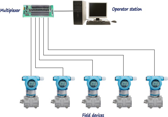
Figure 5. HART multiplexer.
Before installation, manufacturers usually enter device tags and other identification and configuration data into each field instrument. After installation, the instrument identification (tag and descriptor) can be verified in the control room using a configurator (handheld terminal or PC). Many manufacturers offer special software applications for their own products.
HART Communication data
All HART data is grouped into 8-Bit Bytes and organized in messages.
Each Message Packet consists of:
Delimiters | Address | Expansion | Command Byte Count | Data | Check Byte
Delimiter - First byte of the message. Tells message framer where the Byte Count is. Indicates the Message Type.
Address - Indicates the master and slave conversing. 5 bytes long, unique address. Indicates the master and slave communicating.
Expansion - 0-3 bytes reserved for protocol enhancements.
Command - Tells the Application Layer what information is being transferred or action being performed.
Byte Count - Tells message framer where the Check Byte is and the Application Layer how much information is being transferred.
Data - The message "Payload".
Check Byte - An XOR of all message bytes starting with the Delimiter.
Typical Master communication sequence
- The master connects to the channel.
- After the "Link Quiet" timeout the master becomes synchronized to the channel.
- Master obtains the token when: timer expires; or a token pass implied by the message on the network
- Once the master has the token and must begin a transmission with the "Hold" time.
- Once the message is sent, the slave is required to begin its response within Slave Time Out".
- The slave transmits a reply and the master starts the "Link Grant" timer.
- If there is no other master then the "Link Grant" timer expires.
- The master must begin another transmission (i.e., go to step 4)
Basic Design Rules
Although HART networks are very easy to put together, there are still some basic rules that must be followed:
- Minimum loop resistance: For HART communications to occur, you need a minimum loop resistance of 250 ohms. Most HART input/output cards will have this resistance built in. However, if you are using a HART modem, you need to know how long the wire is and the resistance of the wire so that you know if you need to add any resistance. For short runs under 100 meters, it is fairly safe to assume that you need to add a 250 ohm resistor.
- Maximum RC value: For HART communications to occur you must have an RC value of the wire less than 65 μs. The RC value is the total resistance of the circuit multiplied by the total capacitance. The first rule sets the minimum resistance, and this rule sets the maximum. In both cases the more complex the network, the harder this calculation is, and the more important it is. Again, if it is a point-to-point topology and the run is less than 100 meters, then this is not a concern.
- Minimum operating voltage: For all HART devices, there is a minimum voltage that is required for the device to work. This value is different for all devices. If the device does not get the required voltage then it will not operate. If there is too much loop resistance, at a low current the device may power-up however, once the PV begins calculating at high currents, the voltage drop on the loop will increase and the device will turn off. This rule, like the RC rule above, also sets a maximum value on the loop resistance.
- Cable: The choice of the cable matters. As the first two rules imply, the type of cable used will impact the loop resistance and the RC value. For very short runs, HART will run on almost anything. However, as distance increases, the importance of your choice of wire increases as well. Also, the better the cable, the better the noise immunity. In general, you want to pick a shielded twisted pair instrument grade wire and perform the calculations before you buy and install the wires. It is also a good idea to buy a cable designed for HART. Belden 3105A is an example of such a cable.
- Power supply: The power supply specifications are:
Maximum ripple (47 to 125 Hz) = 0.2V p-p
Maximum noise (500 Hz to 10 kHz) = 1.2 mV rms
Maximum series impedance (500 Hz to 10 kHz) = 10 ohm
- Traditional grounding methods for 4-20 mA loops and HART have the shield of the cable connected to ground at one end only. Many installations have been installed in this manner.
WirelessHART
The HART standard has evolved over the years since its first introduction and is now offering a new stage with completely new possibilities for wireless transmission of HART information through a technology called WirelessHART.
WirelessHART is the first standardized wireless communication in the field of process automation. However, as this solution does not include the connection cable, only the digital parameter range is available. The analog measuring signal is not provided.
There are two different WirelessHART solutions: WirelessHART Adapter for enhancing existing HART devices and Self-powered WirelessHART transmitter.
These wireless solutions use the central element of wirelessHART transmission - the WirelessHART gateway for communication. Besides the protocol, the standard also defines various security mechanisms which ensure availability and tap-proof wireless signal transmission. A 2.4 GHz band is used.
WirelessHART uses a flat mesh network where all field devices form a network. Every participating station serves simultaneously as a signal source and a repeater. The original transmitter sends a message to its nearest neighbor, which passes the message on until the message reaches the base station and the actual receiver. In addition, alternative routes are set up in the initialization phase. If the message cannot be transmitted on a particular path, due to an obstacle or a defective receiver, the message is automatically passed to an alternative route. So, in addition to extending the range of the network, the flat mesh network provides redundant communication routes to increase reliability.
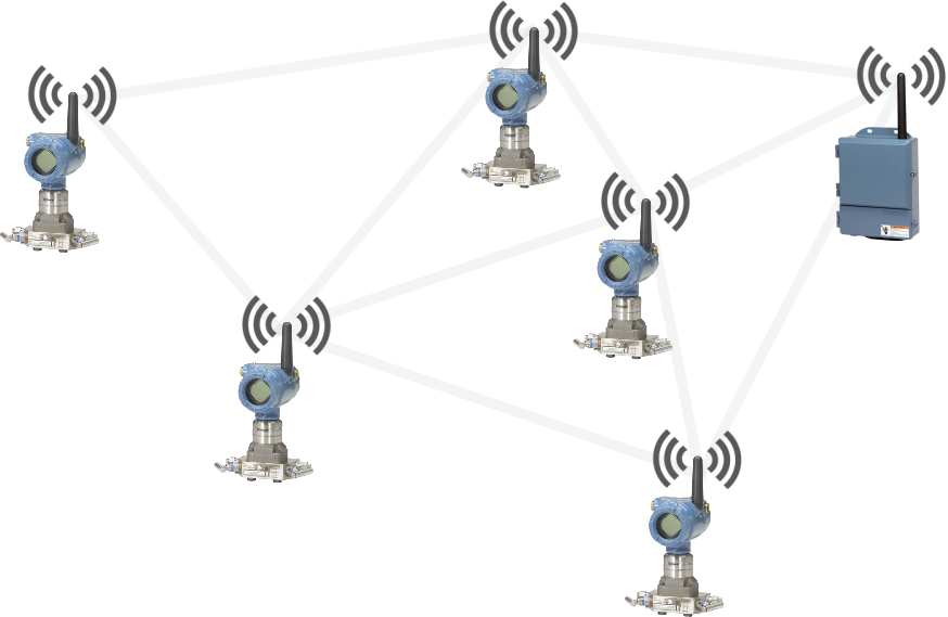
Figure 6. Wireless HART flat mesh network.
The communication in the Wireless Network is coordinated with TDMA (Time Division Multiple Access), which synchronizes the network participants in 10 ms timeframes. This enables a very reliable (collision-free) network, and reduces the lead and lag times during which a station must be active.
To avoid jamming, WirelessHART uses also FHSS (Frequency Hopping Spread Spectrum). All 15 channels as defined in IEEE802.15.4 are used in parallel; WirelessHART uses FHSS to “hop” across these channels. Channels that are already in use are blacked out to avoid collisions with other wireless communication systems. The combination of 10s synchronization and 15 channels allows 1500 communications per second.

0 COMMENTS //
Join the discussion