Intrinsic safety refers to equipment and wiring that’s inherently safe. In other words, an intrinsically safe system is one with energy levels so low they cannot cause an explosion.
The term “Intrinsically Safe” (is) is frequently used to describe any product destined for an explosive area. In reality it is a protection concept based around limiting the available electrical energy to levels so that sparks cannot occur from short circuit or failures which could cause an explosive atmosphere to ignite.
A typical fixed intrinsically safe circuit would comprise a device such as a temperature sensor permanently located within the explosive area, which is in turn protected by a safety barrier located in the safe area. These barriers usually incorporate a series of diodes, resistors and fuses arranged and sized in such a manner that they limit the energy provided to the device in the field.
The "intrinsic safety" protection type, as opposed to other protection types (such as increased safety), refers not only to individual items of equipment, but to the entire circuit.
Intrinsic safety standards mandate design and testing criteria for equipment used in hazardous atmospheres. The essence of intrinsic safety design involves eliminating the source of ignition associated with equipment. This is accomplished by designing the equipment to limit the energy of a potential spark and the temperatures of any surfaces to less than the temperature or energy necessary to ignite gases or vapors present in the atmosphere.
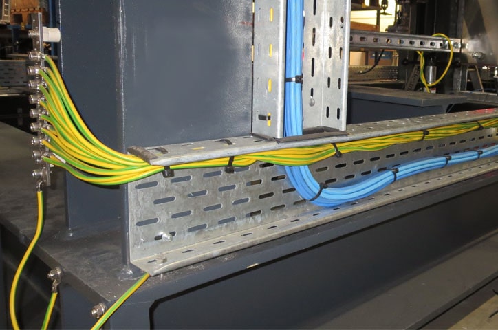
Intrinsically safe wiring should be separated from nonintrinsically safe wires by an air space, a conduit, or a partition.
Certification standards
Across the world, there are differing regulations and requirements which dictate how products are designed, developed, certified and manufactured in order to be sold to a customer as (is) certified. For each country, the device should be tested in accordance with the local requirements. Once tested and certified, products are marked as part of their manufacture.Several different agencies develop standards for intrinsic safety, and evaluate products for compliance with standards. Examples of such agencies in North America are the Factory Mutual Research Corporation, which certifies radios, Underwriters Laboratories (UL) that certifies mobile phones, and in Canada the Canadian Standards Association. In the EU the standard for intrinsic safety certification is the ATEX directive, while in other countries around the world the IECEx standards are followed.
Electrical equipment and items of associated electrical equipment
An intrinsically safe circuit consists of at least one item of electrical equipment and one item of associated equipment. The circuits of the electrical equipment fulfill the requirements of intrinsic safety. Electrical equipment may only be connected to circuits without intrinsic safety via associated equipment. Associated equipment has both intrinsically safe circuits and circuits without intrinsic safety. The circuits are isolated using Zener barriers or electrical isolators. Intrinsically safe electrical equipment and intrinsically safe parts of associated equipment are classed according to EN 60079-11 in safety levels "ia", "ib", and "ic".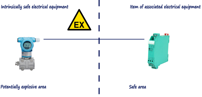
Figure 1. Electrical equipment and items of associated electrical equipment.
Associated equipment like zener diode barriers provide a simple method for implementing intrinsic safety. Their primary drawback is they must be connected to a dedicated intrinsic safety earth ground, which may introduce problems such as electrical noise on the control signal. If a proper ground system is not in place, the cost of installing and properly maintaining it might outweigh the savings of this traditionally inexpensive intrinsic safety solution.
Isolated barriers on other hand provide galvanic isolation for anything connected to them, so there is no need for a dedicated ground. A potential downside is that isolated barriers usually require a separate power supply, although a single supply typically provides power to all barriers inside an enclosure. Galvanically isolated barriers provide protection for specific applications such as transmitters, solenoids, and thermocouples, enabling easy system design.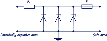
Figure 2. Zener barrier.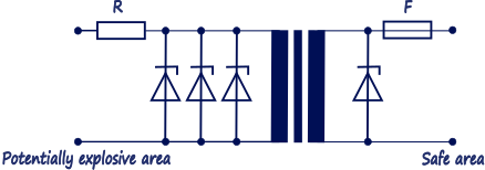
Figure 3. Isolator.
Simple electrical equipment
The ‘simple electrical equipment’ concept allows many simple pieces of apparatus, such as switches, thermocouples, RTD’s and junction boxes to be used in intrinsically safe systems without the need for certification. This gives a significant amount of flexibility in the choice of these ancillaries.
Levels of protection
Intrinsic safety utilizes three levels of protection, ‘ia’, ‘ib’ and ‘ic’ which attempt to balance the probability of an explosive atmosphere being present against the probability of an ignition capable situation occurring.
Ia offers the highest level of protection and is generally considered as being adequately safe for use in the most hazardous locations (Zone 0) because the possibility of two ‘faults’ (see opposite) and a factor of safety of 1.5 is considered in the assessment of safety.
ib apparatus, which is adequately safe with one fault and a factor of safety of 1.5 is considered safe for use in less frequently hazardous areas (Zone 1).
ic apparatus which is assessed in ‘normal operation’ with a unity factor of safety is generally acceptable in infrequently hazardous areas (Zone 2). The ‘ic’ concept is relatively new (2005) and will replace the ‘energy-limited’ (nL) of the type ‘n’ standard IEC 60079-15 and possibly the ‘non-incendive’ concept of North American standards.
Dimensioning of intrinsically safe circuits
The entire intrinsically safe circuit must be protected against the ingress of energy from other sources, and against electrical and magnetic fields. The installation technician or operator is responsible for providing proof of intrinsic safety, not the manufacturer.
The electrical data of the intrinsically safe circuit (voltage, current, power, capacitance, and inductance) should be checked. In the intrinsically safe circuit, all capacitances and inductances must be taken into account and compared with capacitance Co and inductance Lo of the associated equipment. In practice, it is particularly important to observe the capacitance, since this can considerably restrict the length of cables or lines. As a recommended value, capacitance Cc can be taken to be approximately 140…200 nF/km and inductance Lc approximately 0.8…1 mH/km. Where there is any doubt, always assume the worst case.
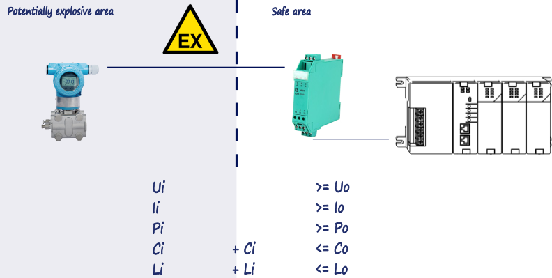
Figure 4. Dimensioning of intrinsically safe circuits.
The voltage (Uo), current (Io) and power (Po) output parameters of the source of power should be compared with the input parameters (Ui, Ii and Pi) of the field device and the output parameters should not exceed the relevant input parameters. Occasionally the safety of the field device is completely specified by only one of these parameters (usually Ui). In these circumstances the unspecified parameters are not relevant. Cc is the permitted cable capacitance and Lc is the permitted cable inductance.
Control cabinet and terminal blocks
In the control cabinet, the intrinsically safe circuits should be clearly marked. The standard does not stipulate a uniform process, but only indicates that the identification should preferably be done by means of a light blue color. The neutral conductors of power cables are usually also identified by the color blue. In this case, intrinsically safe circuits should be identified in a different way, to prevent mix ups. A clear arrangement and spatial separation is advantageous in the control cabinet.
Distances to connection terminal blocks
The air distances between terminal blocks in different intrinsically safe circuits must be at least 6 mm. The air distances between the conductive parts of the connection terminal blocks and conductive parts that can be grounded must be at least 3 mm. Intrinsically safe circuits must be clearly identified.
The distance at modular terminal blocks between the conductive parts of intrinsically safe circuits and the conductive parts of non-intrinsically safe circuits must be at least 50 mm. The spacing can also be created using a partition plate made of insulating material or a grounded metal plate. Cables/conductors of intrinsically safe circuits may not come into contact with a non-intrinsically safe circuit, even if they should become loose from the modular terminal block of their own accord. The cables/conductors must be shortened during installation accordingly.
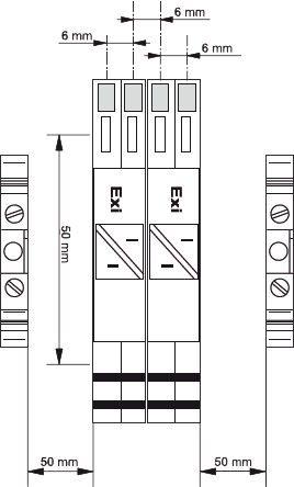
Figure 5. Intrinsically safe terminals.
Quite simply, intrinsic safety is the safest, least expensive, and easiest-to-install method of protection available. With intrinsic safety, system integrity is not a concern because explosions cannot occur. Intrinsic safety systems offer significant labor savings over traditional protection methods because there are no heavy conduits or bolted enclosures. Material costs are less because a standard enclosure is the only major expense for mounting the barriers. With intrinsic safety, low energy requirements eliminate shock hazards and safety “hot” permits so field instruments can be calibrated and maintained while power is on. And unlike most explosion protection methods, intrinsic safety systems operate seamlessly with retrofit applications and with modern technologies such as fieldbus. The affinity to newer technology is one reason intrinsic safety is becoming the dominant protection method.
0 COMMENTS //
Join the discussion