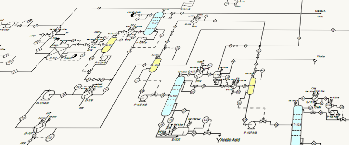
A piping and instrumentation diagram, or P&ID, is a detailed diagram in the process industry which represent the piping and related components of a physical process flow.
Definition and usage
These diagrams show the interconnection of process equipment and the instrumentation used to control the process in the process industry. P&IDs are a schematic illustration of the functional relationship of piping, instrumentation and system equipment components used in the field of instrumentation and control or automation.
The P&ID represents all field instrumentation and control that will be installed on a process and thus is a key document for the control engineers. It shows the field instrumentation that will be wired into the control system, as well as local pressure, temperature or level gauges that may be viewed in the field but are not brought into the control system. Since the instrument tag (tag number) assigned to field devices is shown on this document, the instrument tag associated with, for example, a measurement device or actuator of interest may be quickly found. Also, based on the instrument tags, it is possible to quickly identify the instrumentation and control associated with a piece of equipment.
A standard set of symbols is used to build the diagram, generally based on the International Society of Automation (ISA) Standard S5.1.
It is common practice for the manufacturers and the companies to use their own symbols in order of representing some specific equipment, these symbols are shown in the diagram’s legend along with the standard symbols. Nevertheless the most used are according to ISA.
The diagrams usually contain the following information:
Process piping, sizes and identification, including:
- Pipe classes or piping line numbers
- Flow directions
- Interconnections references
- Permanent start-up, flush and bypass lines
Mechanical equipment:
- Valves and their identifications (e.g. isolation, shutoff, relief and safety valves)
- Control inputs and outputs (sensors and final elements, interlocks)
- Devices - tanks, heaters, coolers
- Miscellanea - vents, drains, flanges, special fittings, sampling lines, reducers and increasers
Control system components:
- Computer control system
- PLC control systems
- Communications connections
- Representation of interlocks, alarms and trips.
- Identification of components and subsystems delivered by others
The P&IDs can provide very clear representation of the whole process which is very useful during the project development, commissioning and exploitation of the industrial plant and process:
Evaluate construction processes - the construction teams can get familiar with the piping traces, and equipment. Instrumentation engineers and technicians can use the P&IDs during the commissioning in order to check if all the instruments are mounted, proof the tag numbers of the equipment etc.
Costs analyze - Form recommendations for cost estimates.
Serve as a basis for controls and programming - orientation for the controls and programming engineers during the development of the control and instrumentation system. Provide information about the scope of delivery of control and instrumentation components.
As basic document when developing - Control and shutdown schemes, Start-up sequences, Safety and regulatory requirements.
Create and implement philosophies for safety and control - basis for the development of system control schemes, like Hazard and Operability Study (HAZOP).
Developing guidelines and standards for facility operation
Process documentation development - basic template for the documentation department when developing manuals and operator guides.
Post commissioning activities - Design a conceptual plan for maintenance and repairs, replace a piece of equipment or guide the design and implementation of a new facility during the plant exploitation.
P&IDs are used by field techs, engineers, and operators to better understand the process and how the instrumentation is interconnected. They can also be useful in training workers and contractors.
Simplified version of P&IDs like the Flow Diagrams can be used for DCS, SCDA or HM screens to provide the plant operators the possibility for better orientation and reaction
Basic symbols and elements
Legend
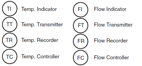
The Legend is part of the P&ID used to define symbols, abbreviations, prefixes and specialized equipment. In order to read a P&ID, the technician needs an understanding of the equipment, instrumentation and technology. The standard and the project specific symbols are usually included and explained in the attached legend, this forms the information needed to interpret and read the diagram. The Legend is found at the front of the P&ID (Figure 1).

Figure 1. Example of P&ID Legend
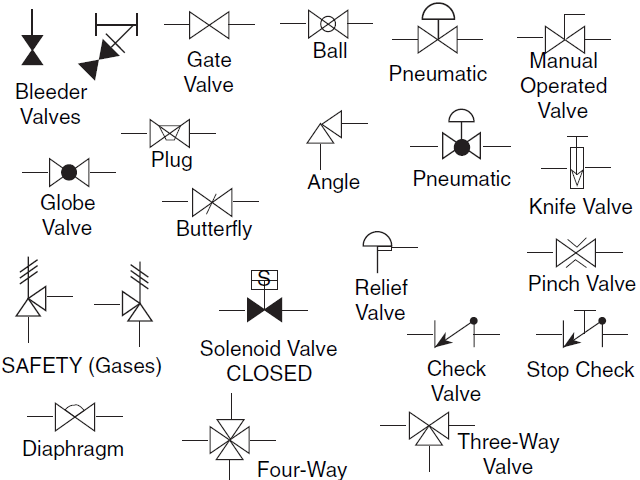
Most common symbols:
- Valve symbols
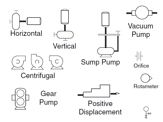
- Equipment symbols
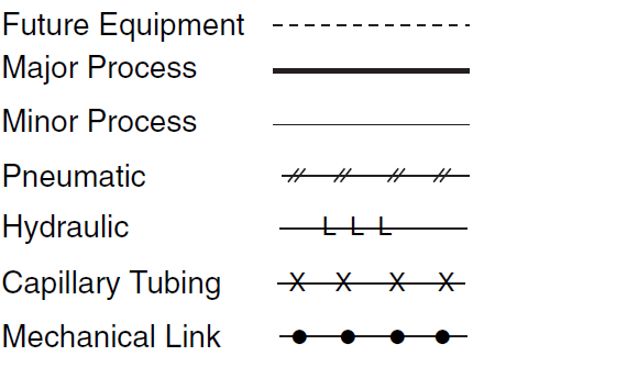
- Line symbols
- Instrument symbols
Identification, Prefixes and TAG Numbers structure
In addition to the legend the identifications of the equipment and symbols are also explained in the legend. The TAG Numbers are also built by combining letters and numbers, this combination contains information about the type of the measurement (pressure, flow, temperature) or for example if this measurement triggers alarm or trip.
For example: PDI1020
PD – Differential pressure
I – Indication
1020 – instrument TAG number, can be used to designate the location of the instrument in the plant
Related articles:
More about P&ID Symbols you can find here
TAG Numbers in process industry used to identify field devices according to ISA-5.1
Process Flow Diagrams, Piping and Instrumentation Diagrams - basic definitions
0 COMMENTS //
Join the discussion