A TAG Number is a code combination of letters and numbers that contains information for the component being represented. The most used standard for tag definition is the one defined by ISA-5.1 - Instrumentation Symbols and Identification.
The ISA-5.1 standard defines a standard tag number convention for valves, transmitters, other field devices, and calculation and control functions. In addition, the standard defines expanded tag number conventions that may better meet the documentation requirements of large installations that consist of many process areas or multiple measurements that serve similar functions.
There are some variations in forming a TAG Numbers:
PI 1005 – Instrument Identification (TAG Number)
PI – Function identification
P – First letter, in this case for Pressure
I – Succeeding letter(s), I - for Indication
1005 – Loop number or instrument number.
The Loop number may contain information like: 10 – Indicates where the instrument is located (for example lube oil system) and 05 – may be the instrument number.
Another approach for forming TAG Numbers:
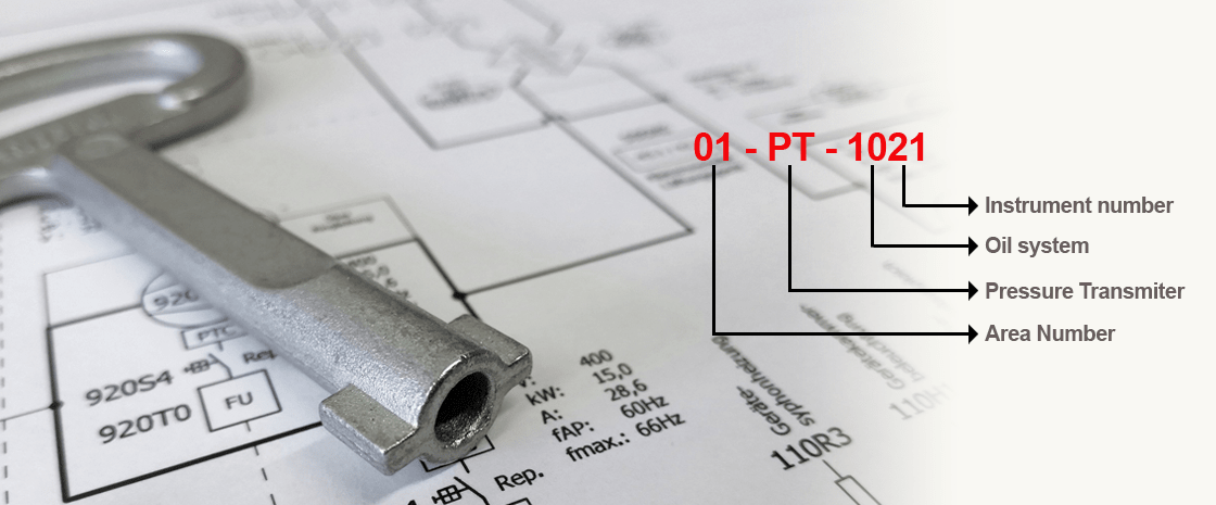
10 PI 1005 03 A - Instrument Identification (TAG Number)
10 – Area number or plant number. Usually not shown on the P&ID, or just indicated with a common comment for the whole document, showing that the equipment belongs to this area.
PI – Function identification
P – First letter, in this case for Pressure
I – Succeeding letter(s), for Indication
1005 – Equipment number or loop number
03 – Optional suffix.
A – Optional Suffix. Often used by 2oo3 (two out of three) voting, to distinguish the instruments. Like:
10 PI 1005 03 A
10 PI 1005 03 B
10 PI 1005 03 C
It is up to the process engineers, plant manufacturers or the end customer to decide how to build their tag numbers.
The letters that make up the first few characters of a typical tag number (“leading letters”) are used to identify the function performed by the field device or by the control system. Following these leading letters is a number. The number that appears on the tag is known as the loop number. The loop numbers are used to uniquely identify devices that are used to perform a specific function.
Devices that are used together to perform a specific function can be assigned the same loop number. For example, the flow transmitter and regulating valve used to measure and regulate the flow of a process stream.
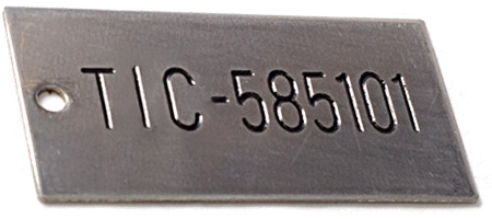
This combination of function letters and numbers allows a field device in a process area to be precisely identified. The tag number assigned to a field device is normally stamped on a tag that is attached to the device (Figure 1).
As defined by ISA-5.1, the identification letters used to specify the function of a field device are organized in a specific manner. The meaning of a letter varies depending on whether it is the first letter or a succeeding letter (Table 1).
| First Letters | Succeeding Letters | ||||
|---|---|---|---|---|---|
| Measured/Initiating Variable |
Variable Modifier |
Readout/Passive Function |
Output/Active Function |
Function Modifier |
|
| A | Analysis | Alarm | |||
| B | Burner, Combustion | User’s Choice | User’s Choice | User’s Choice | |
| C | User’s Choice | Control | Close | ||
| D | User’s Choice | Difference, Differential | Deviation | ||
| E | Voltage | Sensor, Primary Element |
|||
| F | Flow, Flow Rate | Ratio | |||
| G | User’s Choice | Glass, Gauge, Viewing Device | |||
| H | Hand | High | |||
| I | Current | Indicate | |||
| J | Power | Scan | |||
| K | Time, Schedule | Time Rate of Change | Control Station | ||
| L | Level | Light | Low | ||
| M | User’s Choice | Middle, Intermediate | |||
| N | User’s Choice | User’s Choice | User’s Choice | User’s Choice | |
| O | User’s Choice | Orifice, Restriction | Open | ||
| p | Pressure | Point/Test connection | |||
| Q | Quantity | Integrate, Totalize | Integrate, Totalize | ||
| R | Radiation | Record | Run | ||
| S | Speed, Frequency | Safety | Switch | Stop | |
| T | Temperature | Transmit | |||
| U | Multivariable | Multifunction | Multifunction | ||
| V | Vibration, Mechanical Analysis |
Valve, Damper, Louver | |||
| W | Weight, Force | Well, Probe | |||
| X | Unclassified | X-axis | Accessory Devices, Unclassified |
Unclassified | Unclassified |
| Y | Event, State, Presence | Y-axis | Auxiliary Devices, | ||
| Z | Position, Dimension | Z-axis, Safety Instrumented System |
Driver, Actuator | ||
ISA defines some basic rules for the TAG Number Structure regarding the functional identification of an instrument by using letter combinations from Table 1:
- The functional identification of an instrument is based on its function and not on the construction.
If you have a recorder for pressure the identification will be respectively PR P-Pressure and R- Recorder.
A pressure indicator and a pressure-actuated switch connected to the output of a pneumatic level transmitter are identified by LI and LS, respectively. - In an instrument loop, the first-letter of the functional identification is selected according to the measured or initiating variable, and not according to the manipulated variable. Thus, a control valve varying flow according to the dictates of a level controller is an LV, not an FV.
- The succeeding-letters of the functional identification designate one or more readout or passive functions and/or output functions. A modifying-letter may be used, if required, in addition to one or more other succeeding-letters. Modifying-letters may modify either a first-letter or succeeding-letters, as applicable. Thus, PDAL contains two modifiers. The letter D changes the measured variable P into a new variable, "differential pressure." The letter L restricts the readout function A, alarm, to represent a low alarm only.
- The sequence of identification letters begins with a first-letter selected according to Table 1. Readout or passive functional letters follow in any order, and output functional letters follow these in any sequence, except that output letter C (control) precedes output letter V (valve), e.g., PCV, a self-actuated control valve. However, modifying-letters, if used, are interposed so that they are placed immediately following the letters they modify.
- A multiple function device may be symbolized on a diagram by as many bubbles as there are measured variables, outputs, and/or functions. Thus, a temperature controller with a switch may be identified by two tangent bubbles — one inscribed TIC-3 and one inscribed TSH-3. The instrument would be designated TIC/TSH-3 for all uses in writing or reference. If desired, however, the abbreviation TIC-3 may serve for general identification or for purchasing, while TSH-3 may be used for electric circuit diagrams.
- All letters of the functional identification are uppercase.
References:
The International Society of Automation (ISA) www.isa.org.
0 COMMENTS //
Join the discussion