The main temperature-measuring techniques and transducers used in process control include filled- system thermometers, bimetallic thermometers, thermocouples, resistance temperature detectors (RTDs), thermistors and integrated-circuit (IC) temperature sensors.
Resistance Temperature Detectors - RTDs are the second most widely used temperature measurement device because of their inherent simplicity, accuracy, and stability.
In principle, any material could be used to measure temperature if its electrical resistance changes in a significant and repeatable manner when the surrounding temperature changes, however, only certain metals and semiconductors are used in process control for temperature measurement. This type of instruments are called resistance temperature detectors or RTDs.
RTD’s are typically built from Platinum, which change resistance with temperature change, other materials such as Copper and Nickel are also used, but platinum is the most common and has the best linear characteristics of the three, although Nickel has a higher temperature coefficient giving it greater sensitivity.
Resistance temperature devices (RTD) are either a metal film deposited on a former or are wire-wound resistors. The devices are then sealed in a glass-ceramic composite material. The electrical resistance of pure metals is positive, increasing linearly with temperature.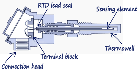
Figure 1. Typical RTD and thermowell construction.
Temperature Coefficient
The temperature coefficient defines how much the resistance will change for a change in temperature, and has units of ohms/oC. The greater the temperature coefficient, the more the resistance will change for a given change in temperature. This ultimately defines how sensitive the device is.
RTD’s are generally quite linear, however the temperature coefficient does vary over the range of operation. As an indication, the temperature coefficient for Platinum is averaged at 0.00385 over the range from 0oC to 100oC, but varies by about 2% over this range.
Selection and Sizing
There are two basic types of RTD's:
- PT100
- PT1000
The ‘PT’ defines that the metal is Platinum and the ‘100’ is the resistance in ohms at ice point (or 0 oC). These are generally wire wound and are quite common.
PT1000 - Again, the ‘PT’ defines a Platinum metal as the sensing element, but a resistance of 1000 ohms can be measured at 0 oC. These are generally thin film devices and are more expensive. 200 and 500 ohm Platinum RTD’s are available, but are more expensive and less common.
Platinum is most popular for RTD's, it has good calibrated accuracy, is quite stable and has good repeatability, but is quite expensive. They are, however, not as sensitive as the Nickel and Balco devices. Nickel is not quite as repeatable, but is less expensive.
The effective range of RTD’s depends principally on the type of wire used as the active element. A Platinum RTD may have a range from -100 °C to 650 °C, whereas a Nickel RTD typically ranges from -180 °C to 300 °C.
Measuring the RTD’S resistance
The most common way of measuring the RTD’s resistance is using the Wheatstone bridge. The Wheatstone Bridge consists of a bridge of three resistors located in the instrument housing and the RTD as the fourth resistor. In a balanced situation, the balancing resistor is adjusted to give zero voltage across the bridge. In an unbalanced configuration, the voltage is measured across the bridge.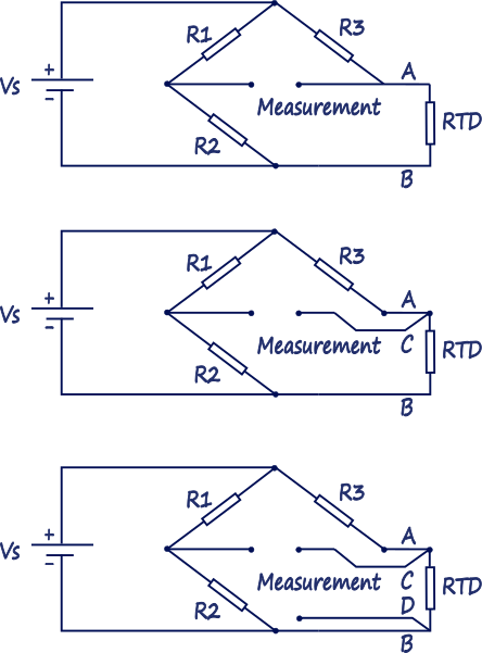
Figure 2. RTD Wheatstone bridge
The most common way to measure RTS’s resistance is to use a Wheatstone bridge.
The Wheatstone Bridge consists of a bridge of three resistors located in the instrument housing, with the fourth resistor being that of the RTD. In a balanced situation, the balancing resistor is adjusted to give zero voltage across the bridge. In an unbalanced configuration, the voltage is measured across the bridge.
In a bridge arrangement, the measurement of the RTD also includes the resistance of the sensing leads. There are three ways to connect up the RTD to a Wheatstone bridge, with the more complex having greater success in overcoming lead resistance problems.
RTD connection to a Wheatstone Bridge
- Two-wire
- Three-wire
- Four-wire
Two-wire measurement:
This is the most basic type of connection for an RTD device. It is used in very simple, cheap applications. They minimise cost at the expense of accuracy. The main problem with two wire measurement is that there is no accounting for the resistance, or even change of resistance in the sensing leads. The measuring device cannot differentiate between the RTD resistance and lead resistance.
Three-wire measurement:
Three-wire measurement with an RTD device balances the resistances in the lead wires within the bridge. Even though this is a simple modification to the two-wire device, it has the added cost of requiring three wires to obtain the measurement. The concept of operation is quite simple in that one lead is measured in the top half of the bridge, with the other lead in the bottom half. Since the sensing distance and other effects are the same, the lead resistance from both sensing leads cancel.
Four-wire measurement - Switched:
One of the limitations with the three-wire measurement, is that if the lead resistance is not the same or suffer different effects, then the measurement will be erroneous. The Four-wire measurement takes both sensing leads into account and alternates the leads into the upper part of the bridge. By alternating, the lead resistance is effectively measured in both sensing leads, but is then cancelled out by taking the average of the two readings. This level of complexity does make four-wire sensing more expensive.
Mounting and Installing RTDs
To protect the thermometer external protective pipe called a thermowell is used. The terminal head houses either the electrical connections, or a locally mounted transmitter.
For optimal performance the whole thermowell should be contacting the medium. The instrument could be mounted in 3 positions:
- Horizontally to the flow
- Perpendicular to the flow
- Under 45°
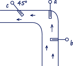
Figure 3. Mounting RTD.
Typical RTD applications
Two-wire RTD’s are generally used in HVAC applications, whereas three-wire RTD’s are commonly found in industrial situations. Four-wire RTD’s are used in high-precision services requiring extremely good accuracy.
Advantages
- Good sensitivity
- Uses standard copper wire
- Copper RTD’s minimise thermocouple effect
RTD's are a little more expensive but are quite stable. They are also very linear, which makes for an easier conversion between the sensing voltage and measured temperature.
Disadvantages
- Bulky in size and fragile
- Slow thermal response time due to bulk
- Self heating problems
- More susceptible to electrical noise
- More expensive to test and diagnose
Drawbacks
Self-heating can be a problem with RTD’s. The magnitude of the errors generated by self-heating effects vary, but are dependent on the size and the resistance of the RTD.
The response time of RTD’s is typically anywhere from 0.5 sec to 5 seconds. The slowness of response is due primarily to the slowness of the thermal conductivity in bringing the device to the same temperature as the surrounds. The response time increases for increased sensor size, also the use of thermowells can double the response time.
For a 2.5 mm probe the response time is 1-2 seconds, this varies with an 8mm probe having a response time of 5-10 seconds.
Related articles:
Temperature measurement Part 1 : Thermocouples
1 COMMENT //
Join the discussion
okmarts online shop 26 Nov 2021
This is a good article. After I read this article, I have learnt many
knowledge about four-wire measurement - switched.