4..20mA signal standard reigns as one of the most popular mediums for signal transmission and electronic control in industrial environments.
The 4-20 mA signal find its place in the field of the industry in the 1950s out of the earlier highly successful 3-15 psi pneumatic control signal standard, when electronics became cheap and reliable enough to emulate the older standard electrically.
Before that process control was realized mechanically. Facilities used pneumatic control signals where controllers were powered by varying pressures of compressed air. Air compression of 3-15 psi became the standard as it was not simple at cheap detecting signals below 3psi, it was easier to differentiate a live zero (3 psi) signal from a failure in the system (0 psi).
The transition was gradual and has extended into the 21st century, due to the huge installed base of 3-15 psi devices and nevertheless pneumatic actuation is still an industry standard. The modern electro-pneumatic positioners use current to pressure (I to P) converters.
4..20mA Current Loops at its vary basic. In fact the whole philosophy is very simple, these loops are based on Ohm’s Law: V = I x RThe voltage (V) is equal to the current (I) multiplied by the resistance (R).
Ohm’s law I=U/R George Simon Ohm (1787 – 1854) was a German physics who in 1826 discovered that there is a direct proportionality between the potential difference (voltage) applied across a conductor and the resultant electric current. This relationship is known as Ohm's law.
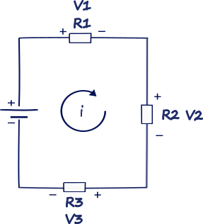
Figure 1. Current loop
Let’s take a look at the diagram. We have voltage power supply which drives the current through the loop and two resistors. At each resistor there is a voltage drop, the voltage can be calculated using Ohm’s Law, but the current will remain constant. So the sensor manufactures use this proportion to design their equipment.
The sensor or instrument generating the signal acts like a current source providing a constant current output signal for a given measurement. The current will always remain consistent at all devices in the loop. As long as there is sufficient voltage, a 4 mA signal generated at the transmitter will still be a 4 mA signal when it reaches the receiver.
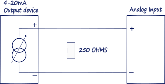
Figure 2. 4..20mA Current loop
Current is measured indirectly, voltage output is produced that is proportional to applied current. In 4-20 mA current loop applications, this is almost always accomplished by applying a shunt resistor of known resistance, then the voltage across the resistor is going to be measured. A typical shunt resistor value is 250 Ohms, since it develops a nice, round voltage drop of 1 Volt for 4 mA and 5 Volts for 20 mA of applied current.
Elements of the 4..20mA current loops
Power Supply. The current loop uses DC power because the magnitude of the current represents the signal level that is being transmitted. If AC power was instead used in the loop, the magnitude of current would be continuously changing, making it difficult to discern the signal level being transmitted. The most common loop power supply voltage is 24V DC, but there are also instances of 12V, 15V, and 36V DC. Some older systems use higher voltages. But the most important thing to remember about the power supply is that it must be set to a level that is greater than the sum of the minimum voltage required to operate the Transmitter, plus the voltage drop in the Receiver, and for long transmission distances, the voltage drop in the wire. Calculating this drop must also consider the maximum level of current that can flow in the 4-20mA current loop—not 20mA, but the over-scale or alarm limit of the transmitter.
Sensor. A sensor typically measures temperature, humidity, flow, level or pressure. The technology that goes into the sensor will vary drastically depending on what exactly it is intended to measure.
Transmitter. This is the device used to transmit data from the sensor. There can be only one Transmitter output in any current loop. It acts like a variable resistor with respect to its input signal and is the key to the 4-20mA signal transmission system. The transmitter converts the real world signal, such as flow, speed, position, level, temperature, humidity, pressure, etc., into current. The level of loop current is adjusted by the transmitter to be proportional to the actual sensor input signal. The transmitter typically uses 4mA output to represent the calibrated zero input or 0%, and 20mA output to represent a calibrated full-scale input signal or 100% as shown in Figure 3 below: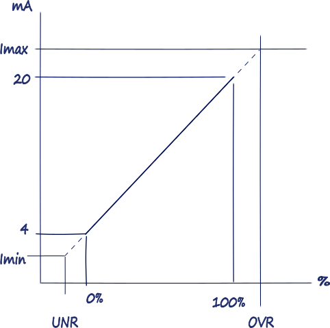
Figure 3.
The relationship between the output current value and process variable measurement is set by calibration of the transmitter, which assigns a different range of engineering units to the span between 4 and 20 mA. In some transmitters, the mapping between the sensor engineering units and output current can even be inverted, such that 4mA represents the full-scale process variable, and 20mA the minimum process signal.
There are two main types of transmitters: 2 Wire and 4 Wire.
Receiver. This is the device at the other end of the transmission line that “receives” the transmitted signal. In a 4-20mA process loop, the Receiver could be located from couple of meters to hundreds of meters away from the transmitter. The current is not measured directly, it is done indirectly by measuring the voltage dropped across a resistor of known value, and then use Ohm’s Law to calculate actual current.

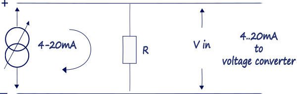
Figure 4. 4..20mA to voltage converter
The voltage generated across the internal resistance of the Receiver is the signal which the Receiver processes. The loop power supply must be sufficient to drive the voltage produced across the load of the receiver at maximum current, plus the voltage drop in the wiring, and all the while maintaining the minimum voltage required by the transmitter to maintain operation. Depending on the source of current for the loop, receiver devices may be classified as active (supplying power), or passive (relying on loop power).
The fundamental principles of electricity is that current is the same at all points in a closed current loop. This is why the 4-20 mA current loop is the ideal analog standard for transmitting information over long distances, and through multiple meters, transmitters, data loggers, and other 4-20 mA loop devices. The current will always remain consistent at all devices in the loop. As long as there is sufficient voltage, a 4 mA signal generated at the transmitter will still be a 4 mA signal when it reaches the receiver.
Related articles
0 COMMENTS //
Join the discussion