Safety Integrity Level (SIL) defines the requirements that a device or a system is expected to fulfill so that the failure probability can be specified. The aim of SIL is to achieve maximum possible operational reliability.
All industrial machines and plants are potentially hazardous. In order to protect personnel and environment from hazard and machines and plants from damage, risk should be determined and afterwards reduced by applying suitable measures.
Risk = Probability of the occurrence of a hazardous event x Consequences (costs) of a hazardous event.
Reduction of risks
Everyday hazards are assessed according to their risk level, and accepted or not. If someone plans climbing a mountain a proper selection of equipment and route will minimize the risk of an accident. The traveler can reduce the hazard to a residual risk which is acceptable for him. But there is always a residual risk.
Protective measures
We can protect ourselves by reducing the probability of the occurrence of a hazard or by limiting its effect. Our world is being increasingly dominated by electrical and electronic systems. These systems have increased the number of potential hazards we have, but these systems can also be used to prevent or mitigate the consequences of these hazards.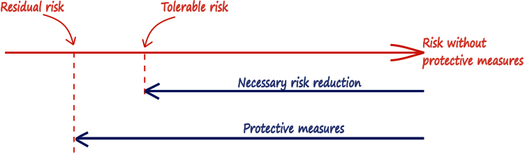
Figure 1. SIL Risk reduction.
This accepted residual risk must be assessed individually. What is acceptable for one person may be unacceptable for someone else. It depends on region/country, laws, costs.
Protective measures in industry
There are different measures for reducing the risk: Structural measures (e.g. build concrete walls around production plants); Distribution of hazards; Evacuation plans; Safety-relevant control and protection equipment.
The approaches that are used for reducing the risk are also called layers of protection. These different layers of protection are structured hierarchically and are to be viewed independently of each other and their functions are not connected to each other. Low level applications should not be used simultaneously for safety application of higher level. In this way if one layer fails the next layer takes over to limit or avoid damage.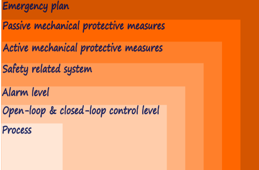
Figure 2.Protective layers
Overall risk reduction results from the measures of the individual layers of protection and must result in an acceptable residual risk. The measures which are finally applied frequently depend on how high the residual risk may be while still being acceptable - and what costs are necessary to achieve this. Safety-relevant control and protection equipment can make a significant contribution to reducing risks in machinery and plants.
A uniform standard for plants in the process industry is adopted in 2003. The following two standards are of significance to process instrumentation:
- EC 61508 (basic standard): Globally applicable as the basis for specifications, design and operation of safety-related systems .
- EC 61511 (application-specific standard for the process industry): Implementation of IEC 61508 for the process industry.
Functional Safety is part of the overall safety of a system that depends on the correct functioning of safety-related (sub)systems and external equipment for risk reduction. This means that Functional Safety covers only one aspect of overall safety. Other issues such as electrical safety, fire and radiation protection, etc. do not fall within the scope of Functional Safety.
In the latest control systems the safety functions are performed mainly by programmable logic controllers (PLC) therefore the main challenge is to ensure the correct functioning of these systems. It is therefore essential to establish suitable methods for preventing systematic faults (usually due to human error committed during the specification and implementation phase) and for controlling failures, abnormalities and loss of function (usually physical phenomena). In this context the expression "functional safety of the protective or safety function" is used.
IEC 61508 defines appropriate methods for achieving functional safety for associated systems.
Safety Instrumented System (SIS)
A Safety Instrumented System (SIS) is defined as an instrumented system used to implement one or more Safety Instrumented Functions (SIF). A SIS is composed of any combination of sensors, logic solvers and final control elements for the purpose of taking a process to a safe state when predetermined conditions are violated. SIS is used to secure a hazardous process and to reduce the risk of an accident. To be able to evaluate the functional safety of an SIS all units have to be take into account, from sensor up to actuator.
A SIF is a function to be implemented by a SIS that is intended to achieve or maintain a safe state for the process with respect to a specific hazardous event.
To help companies implement a SIS, the International Electrotechnical Commission (IEC) has developed IEC 61508, the standard for “Functional Safety of Electrical/Electronic/Programmable Electronic Safety Related Systems”.
The main objective of IEC 61508 is to provide a design standard for Safety Instrumented Systems to reduce risk to a tolerable level by following the overall hardware and software safety life cycle procedures, and by maintaining the associated stringent documentation.
IEC 61508 has become the benchmark used mainly by safety equipment suppliers to show that their equipment is suitable for use in Safety Integrity Level (SIL) rated systems.
Determining required SIL level
The single components of a plant or machine may have different levels of risk. As the risk increases, the demands made on the safety instrumented system (SIS) also increase.
The standards IEC 61508 and IEC 61511 therefore define four different safety levels which describe the measures for handling the risks of these components. These four safety levels are the safety integrity level (SIL) defined by the standards. From SIL1 for a low risk levels up to SIL4 high risk.
The higher the number of the safety integrity level (SIL), the higher the reduction of the risk. The SIL is therefore a relative measure of the probability that the safety system can correctly provide the required safety functions for a specific period.
SIL represents a measure for the probability that the Safety Instrumented System (SIS) can correctly perform the specified safety functions for a certain time period.
To determine a SIL, the safety practitioner team RISK/PROCESS HAZARD ANALYSIS (PHA) identifies all process hazards, estimate their risks and decide if that risk is tolerable. Once a SIL has been assigned to a process, the safety practitioner has to verify that the individual components (sensors, logic solvers, final elements, etc.) that are working together to implement the individual Safety Instrumented Functions (SIF) comply with the constraints of the required SIL.
For any device used in a SIS, the team must pay close attention to each device’s Safety Failure Fraction (SFF) and Probability of Failure on Demand (PFDavg). For each device in the SIF, both of these numbers have to be compared to the rules outlined in the safety standards to ensure that they are sufficient for use in the required SIL of the SIS.
It is always the responsibility of the end user to perform or verify the calculations for the entire safety loop. Since a SIF relies on more than one device, it is imperative that all devices in the loop work together to meet the required SIL levels. The device’s SFF and the PFDavg values used for these calculations can be found in a FMEDA report.
Info: Failure modes, effects, and diagnostic analysis (FMEDA) is a systematic analysis technique to obtain subsystem / product level failure rates, failure modes and diagnostic capability.
There are different approaches for determining the required SIL of a plant or plant component. The standards IEC 61508 and IEC 61511 include various methods for defining the SIL. Since the topic is extremely complex, only what is needed to obtain a basic understanding is presented here.
A quantitative method
The risk of a hazardous process is determined by the probability with which a hazardous event could occur (without existing protective measures), multiplied by the effect of the hazardous event. It is necessary to determine how high the probability is which can lead to a hazardous state.
This probability can be estimated by applying quantitative risk assessment methods, and defined by a numeric limit.
The probability can be determined by:
- Analysis of failure rates in comparable situations
- Data from relevant databases
- Calculation with application of appropriate prediction methods
The exact methods of calculation cannot be treated further here. If required, details can be found in IEC 61508 Part 5.
A qualitative method
The qualitative method is a simplified model which readily shows which SIL is required for which hazards.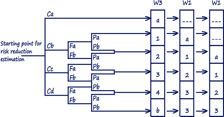
Figure 3. Determination of SIL according to the “qualitative method”.
C = Consequence risk parameter
F = Frequency and exposure time risk parameter
P = Possibility of failing to avoid hazard risk parameter
W = Probability of the unwanted occurrence
--- = No safety requirements
a = No special safety requirements
b = A single SIS is not sufficient
1, 2, 3, 4 = Safety integrity level
| Extent of damage | |
|---|---|
|
Ca |
Light injury of a person, small environmental damage |
|
Cb |
Severe injury or death of a person |
|
Cc |
Death of several persons |
|
Cd |
Death of many persons |
| Duration of exposure time in the hazardous area | |
|---|---|
|
Fa |
Seldom to frequent |
|
Fb |
Frequent to permanent |
| Possibility of avoiding the hazardous event |
|
|---|---|
|
Pa |
Possible under certain conditions |
|
Pb |
Almost impossible |
| Probability of occurence | |
|---|---|
|
W1 |
Verly low |
|
W2 |
Low |
|
W3 |
Relatively high |
Demand modes. Low and High demand
Since applications in the process and production industries vary greatly, different demands are also placed on the safety instrumented system (SIS). For this reason, each of these industrial sectors has a different system in which the demand rate on the SIS is defined. A differentiation is made between the systems using the probability of SIS failure on demand (PFD).
Low demand. Mode with low demand rate on the safety system. There must not be a demand on the safety system more frequently than once per year. Low demand mode (on demand) is typically found in the process industry. A typical example is an emergency shutdown system which only becomes active when the process becomes out of control. This normally occurs less than once a year. For this reason, high demand mode is usually of no significance for process instrumentation in most cases.
| SIL | PFD | Max. accepted failure of SIS |
|---|---|---|
|
SIL 1 |
10-2 ≤ PFD < 10-1 |
One hazardous failure in 10 years |
|
SIL 2 |
10-3 ≤ PFD < 10-2 |
One hazardous failure in 100 years |
|
SIL 3 |
10-4 ≤ PFD < 10-3 |
One hazardous failure in 1,000 years |
|
SIL 4 |
10-5 ≤ PFD < 10-4 |
One hazardous failure in 10,000 years |
Table1. Failure limits for a safety function used in low demand mode.
High demand. Mode with high demand rate or continuous demand on the safety system. The safety system works continuously or has a demand more frequently than once per year. High demand mode (continuous mode) is mainly used in production engineering. Continuous monitoring of working processes is frequently required here to guarantee the safety of humans and the environment.
| SIL | PFH (per hour) | Max. accepted failure of SIS |
|---|---|---|
|
SIL 1 |
10-6 ≤ PFD < 10-5 |
One hazardous failure in 100,000 hours |
|
SIL 2 |
10-7 ≤ PFD < 10-6 |
One hazardous failure in 1,000,000 hours |
|
SIL 3 |
10-8 ≤ PFD < 10-7 |
One hazardous failure in 10,000,000 hours |
|
SIL 4 |
10-9 ≤ PFD < 10-8 |
One hazardous failure in 100,000,000 hours |
Table 2. Failure limits for a safety function used in high demand mode.
Failure rates
The analysis of possible failure sources is of significant importance for the safety of a system. When considering λ failure rates, distinction is made as to which failures are classified as dangerous and which as safe and consequently without impact on the correct execution of a safety function. Furthermore, the diagnostic coverage of a failure is examined.
Safe Failure Fraction (SFF)
The SFF value (Safe Failure Fraction) describes the fraction in percent of safe failures and detected dangerous failures related to the total failure rate. Failures are considered as non-hazardous if they cannot put the system in a dangerous state. The higher the value, the lower the probability of a dangerous system failure. A value of 62 % signifies that 62 out of 100 failures do not have an impact on the safe system function.
Hardware Failure Tolerance (HFT)
HFT (Hardware Fault Tolerance) is the ability of a functional element to further perform a required safety function in spite of the presence of faults or deviations. A hardware fault tolerance of N means that N + 1 faults could cause a loss of the safety function. For example with a hardware fault tolerance of 0, a single fault can lead to the failure of the safety function. In general, HFT can be increased by creating a redundant system architecture.
Device Type
IEC 61508 distinguishes between simple and complex devices.
Simple type A elements Type A devices are "simple" units for which the failure behavior of all components is completely known. They comprise e.g. relays, resistors and transistors, however no complex electronic components such as e.g. microcontrollers.
Complex type B devices
Type B devices are "complex" units containing electronic components such as microcontrollers, microprocessors and ASICs. For these components and in particular for software controlled functions, it is highly difficult to completely anticipate all faults. The more complex the device, the higher the requirements. The following tables show that higher requirements apply to type B devices than to type A devices.
| SFF (Safe Failure Fraction) |
HFT (Hardware Fault Tolerance) |
||
|---|---|---|---|
|
0 |
1 |
2 |
|
|
< 60 % |
SIL 1 |
SIL 2 |
SIL 3 |
|
60 % to < 90 % |
SIL 2 |
SIL 3 |
SIL 4 |
|
90 % to < 99 % |
SIL 3 |
SIL 4 |
SIL 4 |
|
≥ 99 % |
SIL 3 |
SIL 4 |
SIL 4 |
Table 3. SFF and HFT for type A devices.
| SFF (Safe Failure Fraction) |
HFT (Hardware Fault Tolerance) |
||
|---|---|---|---|
|
0 |
1 |
2 |
|
|
< 60 % |
not allowed |
SIL 1 |
SIL 2 |
|
60 % to < 90 % |
SIL 1 |
SIL 2 |
SIL 3 |
|
90 % to < 99 % |
SIL 2 |
SIL 3 |
SIL 4 |
|
≥ 99 % |
SIL 3 |
SIL 4 |
SIL 4 |
Table 4. SFF and HFT for type B devices.
Mean Time Between Failures (MTBF)
The mean operating time between failures in years describes the theoretical operating time between two subsequent failures and allows to measure reliability. By no means should this figure be mixed up with lifetime or useful lifetime of the system.
Types of fault
A differentiation is made in a safety instrumented system (SIS) between systematic faults and random faults. Both types of faults must be considered individually in order to fulfill a demanded SIL.
Random faults
Random faults do not exist at the time of delivery. They result from failure of individual components of the hardware, and occur at random during operation. Examples of random faults include: Short-circuit, open-circuit, drift in component values, etc. The fault probability and the associated failure probability can be calculated. The individual hardware components of a SIS are calculated. The results are expressed by the PFD value (average probability of failure on demand), and are the calculation basis for determining the SIL value.
Systematic faults
Systematic faults already exist at the time of delivery of every device. These are typically development faults or faults in the design or configuration. Examples include software faults, incorrect dimensioning, incorrect rating of measuring device, etc. Faults in the device software make the largest contribution to the systematic faults. The fundamental consideration with systematic software faults is that faults in the programming can also result in faults in the process.
Common cause faults
Common cause faults of the hardware can be caused by external factors, such as electromagnetic interference (EMC) or other environmental factors, such as temperature or mechanical load. They have a simultaneous effect on multiple components of a “safety-related system”.
When using devices in a redundant configuration, systematic faults are common cause. As a result, special measures must be used to avoid systematic faults during development. This includes, for example, qualitative requirements of the IEC standard for the development process, the change process, and the HW/SW architecture of the device.
The device manufacturer must provide data on the SIL rating with respect to systematic faults. This information is usually present in the conformity certificate of the individual devices. This information can be supported by certificates produced by independent organizations or companies specialized in testing.
This rating is not part of quantitative calculations, but only provide information on the SIL rating of the device with respect to systematic faults.
In order to fulfill the systematic fault requirements for a certain SIL (e.g. SIL 3), the complete SIS must be appropriately designed. The simplest consideration in this case is that all components possess a SIL 3 rating for systematic faults.
Example technique for evaluating probabilities of failure can be found in IEC 61508 Part 6.
0 COMMENTS //
Join the discussion