The process of measuring a fluid is called Flow Measurement. Flow measuring devices may be Coriolis, vortex, magnetic, ultrasonic, differential pressure, turbine and positive displacement meters.
Basic Terms in the flow measurement
Velocity is a measure of speed and direction of an object. When related to fluids it is the rate of flow of fluid particles in a pipe. The speed of particles in a fluid flow varies across the flow. Where the fluid is in contact with the constraining walls the velocity of the liquid particles is virtually zero; in the center of the flow the liquid particles will have the maximum velocity. Thus, the average rate of flow is used in flow calculations. The units of flow are normally feet per second (fps), feet per minute (fpm), meters per second (mps), and so on.
Viscosity is a property of a gas or liquid that is a measure of its resistance to motion or flow, it can be described as the fluids “thickness”. Viscous liquids such as syrup has a much higher viscosity than water and water has a higher viscosity than air. Viscous liquids flow very slowly and it is very hard to move an object through them. Typically the viscosity of a liquid decreases with increasing the temperature.
Flow patterns can be considered to be laminar, turbulent, or a combination of both.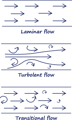
Figure 1. Flow types. Lamirar, turbulent and transitional flows.
Laminar flow of a liquid occurs when its average velocity is comparatively low and the fluid particles move smoothly in layers, as shown in Figure 2a. The velocity of the particles across the liquid takes a parabolic shape. In laminar flow, the fluid moves smoothly in orderly layers, with little or no mixing of the fluid across the flow stream. With laminar flow, there can still exist changes in velocity as the friction of the wall slows the layers closest to the wall, while the flow in the centre of the pipe moves faster. This velocity change produces a parabolic streamlined flow profile.
Turbulent flow occurs when the flow velocity is high and the particles no longer flow smoothly in layers and turbulence or a rolling effect occurs. This is shown in Figure 2b. In turbulent flows, the laminar flow breaks down and the layers are mixed. Turbulent flow is quite random, as smaller currents flow in all directions - these are also known as eddies. This type of flow has a flatter flow profile, such that the velocity of forward flow in the centre of the pipe is nearly the same as that near the walls of the pipe.
Figure 2. Flow velocity variations across pipe; (a) laminar flow, (b) turbulent flow.
Pulsations. In maintaining good measuring conditions, pulsations in the flow stream should be recognised and avoided if possible. Common causes of pulsating flows are from pumps, compressors and two-phase fluids.
Cavitation. This condition occurs when the pressure is reduced below the vapour pressure of the liquid. This causes vapour cavities, or bubbles, to form. These bubbles can dissipate quickly causing damage to the piping system as well as the flowmeter, resulting in measurement errors. Maintaining sufficient pressure in the pipe commonly solves the problem. In applications where this is likely, measurement methods requiring a pressure drop should be avoided, such as differential pressure devices.
Swirl occurs with laminar flows as fluid passes through elbows or some other form of pipeline geometry. In a similar fashion to turbulent flows, they affect the measurements of many instruments and to avoid disturbances measuring devices should be mounted downsteam from the swirling fluid. The effects of swirls can be minimised by the use of a flow conditioner.
Figure 3. Flow straightener.
Reynolds number defines the flow conditions at a particular point. It is a way of representing fluidity and is a useful indicator of laminar and turbulent flow. Laminar flow exists if the Reynolds number is less than 2000, and turbulence when the number is above 4000. There is not a clear transition between laminar and turbulent flows, which does complicate flow measurement in this range of operation.
The Reynolds number R is a derived relationship combining the density and viscosity of a liquid with its velocity of flow and the cross-sectional dimensions of the flow:
R = VDρ / µ
V – average fluid velocity
D – diameter of the pipe
ρ – density of the liquid
µ - absolute viscosity
The Bernoulli equation is an equation for flow based on the law of conservation of energy, which states that the total energy of a fluid or gas at any one point in a flow is equal to the total energy at all other points in the flow. Most flow equations are based on the law of energy conservation and relate the average fluid or gas velocity, pressure, and the height of fluid above a given reference point. This relationship is given by the Bernoulli equation. The equation can be modified to take into account energy losses due to friction and increase in energy as supplied by pumps.
Energy losses in flowing fluids are caused by friction between the fluid and the pipe walls and objects. In most cases these losses should be taken into account.
Mass flow is a measure of the actual amount of mass of the fluid that passes some point per unit of time.
Total flow is the volume of liquid flowing over a period of time and is measured in gallons, cubic feet, liters and so forth.
Volumetric flow rate represents that volume of fluid which passes through a pipe per unit of time. This form of measurement is most frequently achieved by measuring the velocity of a fluid with a DP sensor as it travels through a pipe of known cross sectional area.
Flow Measurement Instruments
Flow is usually being measured by indirect measurements. Flow measurements are divided in some groups: differential pressure, velocity, volumetric, and mass.
Differential-pressure flowmeters measure flow by inferring the flow rate from the drop in differential pressure (dP) across an obstruction in the process pipe, which can be directly related to flow rate. Some of the common dP flowmeters are orifice plates, venturi tubes, flow nozzles, wedge flow meters, pitot tubes, and annubars.
The orifice plate is the most common type of restriction used in process control applications to measure flow, it is a simple metal diaphragm with a constricting hole. The diaphragm is normally clamped between pipe flanges to give easy access. The lagging edge of the hole in the diaphragm is bevelled to minimize turbulence. 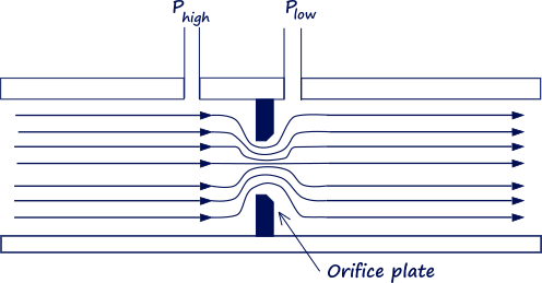
Figure 4. Orifice plate used to create pressure drop.
There pressure decreases as the flow velocity increases through the restriction. The lowest pressure occurs where the velocity is the highest. Downstream where the fluid expands back into a larger area, velocity decreases and pressure correspondingly increases. The pressure downstream of the orifice plate never returns completely to the pressure before the orifice as the restriction creates friction and turbulence causing energy loss.
The differential pressure across the orifice plate is a measure of the flow velocity. The greater the flow, the larger the differential pressure across the orifice plate.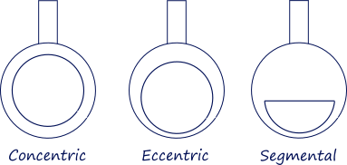
Figure 5. Orifice types: Concentric; Eccentric; Segmental.
Eccentric and segmental orifices are mainly used for measuring unclean liquids as well as gas or vapor where liquids may be present. Where the stream contains particulate matter, the segmental orifice may be preferable because it provides an open path at the bottom of the pipe.
The Venturi tube uses the same differential pressure principle as the orifice plate. The Venturi tube normally uses a specific reduction in tube size, and is not used in larger diameter pipes where it becomes heavy and excessively long. The advantages of the Venturi tube are its ability to handle large amounts of suspended solids, it creates less turbulence and hence less insertion loss than the orifice plate. The differential pressure taps in the Venturi tube are located at the minimum and maximum pipe diameters. The Venturi tube has good accuracy but has a high cost.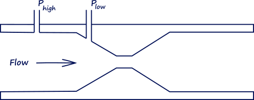
Figure 6. Venturi tube.
The flow nozzle is a good compromise on the cost and accuracy between the orifice plate and the Venturi tube for clean liquids. It is not normally used with suspended particles. Its main use is the measurement of steam flow. The flow nozzle consists of a restriction with an elliptical, or near elliptical, contour approach section that terminates in tangency with a cylindrical throat section. Flow nozzles are commonly used to measure steam flow and other high-velocity fluid flows where erosion may be a problem. Since the exact contour of the nozzle is not particularly critical, the flow nozzle can be expected to retain precise calibration for a long time under hostile conditions.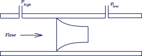
Figure 7. Flow nozzle.
Benefit of the Dall Tubes is that they have the low permanent pressure loss. Up to 97% of the DP generated can be recovered. Dall tubes are used for a number of process conditions and are suited for gas transmission pipelines, where significant pressure loss is not tolerated. Dall Tubes are ideal for clean fluids and not suited for fluids with suspended solids.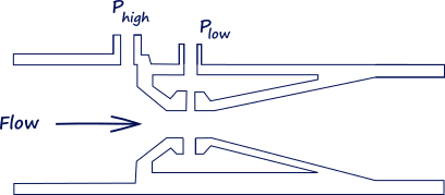
Figure 8. Dall tube.
The elbow can be used as a differential flow meter. Figure 9a shows the cross section of an elbow. When a fluid is flowing, there is a differential pressure between the inside and outside of the elbow due to the change in direction of the fluid. The pressure difference is proportional to the flow rate of the fluid. The elbow meter is good for handling particulates in solution, with good wear and erosion resistance characteristics but has low sensitivity.
The pilot static tube shown in Figure 9b is an alternative method of measuring the flow rate, but has some disadvantages in measuring flow, in that it really measures the fluid velocity at the nozzle. Because the velocity varies over the cross section of the pipe, the Pilot static tube should be moved across the pipe to establish an average velocity, or the tube should be calibrated for one area. Other disadvantages are that the tube can become clogged with particulates and the differential pressure between the impact and static pressures for low flow rates may not be enough to give the required accuracy.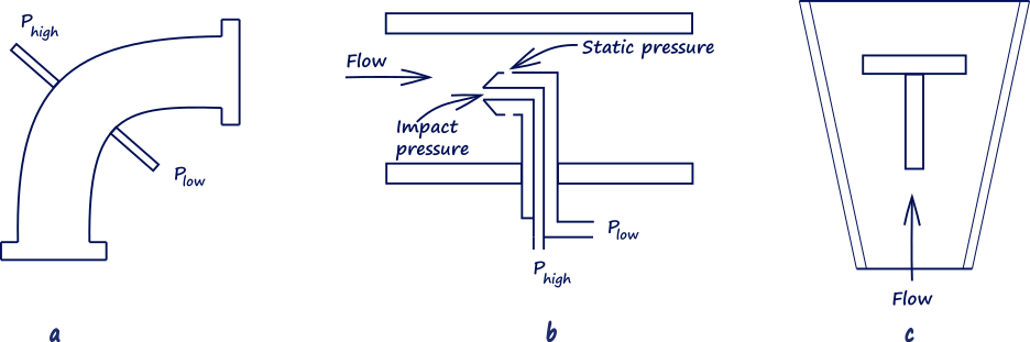
Figure 9. Flow measuring devices: (a) Elbow; (b) pilot static tube; (c) rotameter.
The rotameter is a vertical tapered tube with a T (or similar) shaped weight. The tube is graduated in flow rate according to the specifics of the gas or liquid flowing up the tube. The velocity of a fluid or gas flowing decreases as it goes higher up the tube, due to the increase of the tube’s diameter. Eventually a point is reached where the force on the weight due to the flowing fluid is equal to that of the weight. The rotameter can be used to measure differential pressures across a constriction or flow in both liquids and gases.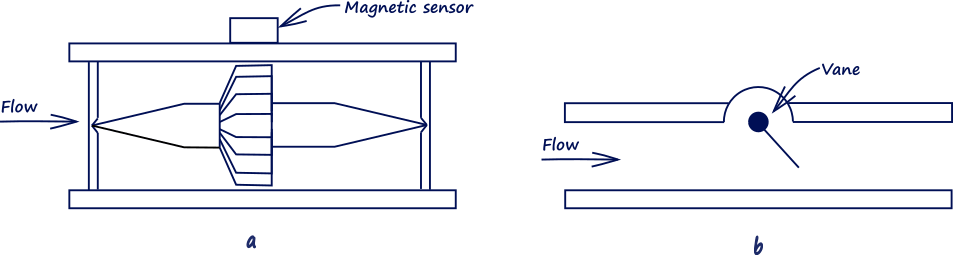
Figure 10. Flow rate measuring devices. (a) Turbine; (b) moving vane.
The turbine flow meter, shown in Figure 10a, is a turbine flow rate device. The turbine rotor is mounted in the centre of the pipe and rotates at a speed proportional to the rate of flow of the fluid or gas passing over the blades. The turbine blades are normally made of a magnetic material or ferrite particles in plastic so that they are unaffected by corrosive liquids. As the blades rotate, they can be sensed by a magnetic sensor attached to the pipe. The turbine should be only used with clean fluids such as gasoline. The rotating flow devices are accurate with good flow operating and temperature ranges but more expensive than most of the other devices.
On Figure 10b is shown a moving vane. This is much simpler. The vane can be spring loaded and able to pivot; by measuring the angle of tilt the flow rate can be determined.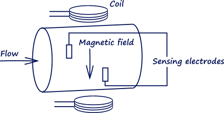
Figure 11. Magnetic flowmeter.
The magnetic flowmeter is constructed of a nonmagnetic pipe that carries the flowing liquid, which must have a minimum level of conductivity. On both sides of the pipe are mounted magnetic coils and cores that provide a magnetic field across the full width of the metering pipe when electric current is applied. The fluid flowing through the pipe is the conductor, and as the conductor moves through the magnetic field a voltage is generated that is proportional to the volumetric flow rate. There is no insertion loss and the readings are independent of the fluid characteristics, but it is a relatively expensive instrument.
Vortex flow meters are based on the principle that an obstruction in a fluid or gas flow will cause turbulence or vortices, or in the case of the vortex precession meter (for gases), the obstruction is shaped to give a rotating or swirling motion forming vortices and these can be measured ultrasonically. The frequency of the vortex formation is proportional to the rate of flow and this method is good for high flow rates. At low flow rates the vortex frequency tends to be unstable.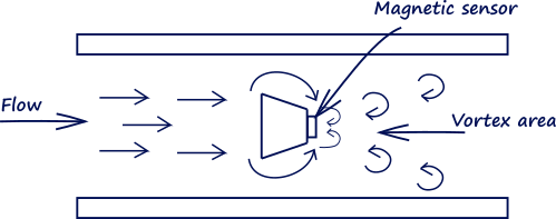
Figure 12. Vortex shedding flow device.
Selection
Choosing a particular device for a specific application depends on a number of factors such as- reliability, cost, accuracy, pressure range, temperature, wear and erosion, energy loss, ease of replacement, particulates, viscosity, and so forth. The choice of the measuring device will depend on the required accuracy and fluid characteristics (gas, liquid, suspended particulates, temperature, viscosity, and so on.)
The general purpose and most commonly used devices are the pressure differential sensors used with pipe constrictions. These devices will give accuracies in the 3 percent range when used with solid state pressure sensors which convert the readings directly into electrical units or the rotameter for direct visual reading.
The Venturi tube has the highest accuracy and least energy loss followed by the flow nozzle and the orifice plate. For cost effectiveness the devices are in the reverse order. If large amounts of particulates are present, the Venture tube is preferred. The differential pressure devices operate best between 30 and 100 percent of the flow range. The elbow should also be considered in these applications.
Installation
Because of the turbulence generated by any type of obstruction in an otherwise smooth pipe, the placement of flow sensors is very important. The position of the pressure taps can be critical for accurate measurements. The manufacturer’s recommendations should be followed during installation.
0 COMMENTS //
Join the discussion