A standard set of symbols is used by the process engineers when designing the Piping and Instrumentation diagrams. The first thing to do when reading P&ID is do get to know the symbol's legend.
Like other specialized diagrams, P&IDs are built up of standard shapes and symbols. There is a huge variety of symbols, depending on industry and manufacturer. Most industries have standardized their symbol representation according to the ISA Standard S5.1 Instrumentation Symbol Specification and use them to design: P&IDs, Flow Diagrams, Logic Plans.
The shapes in the legend are representative of the functional relationship between piping, instrumentation, and system equipment units.
They can be broken to some main groups:
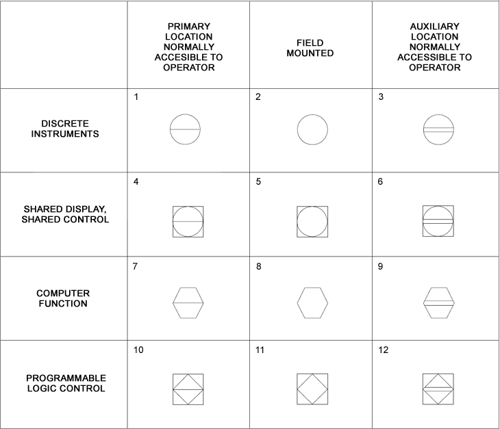
- general instrument or function symbols
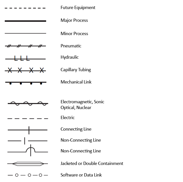
- instrument line symbols
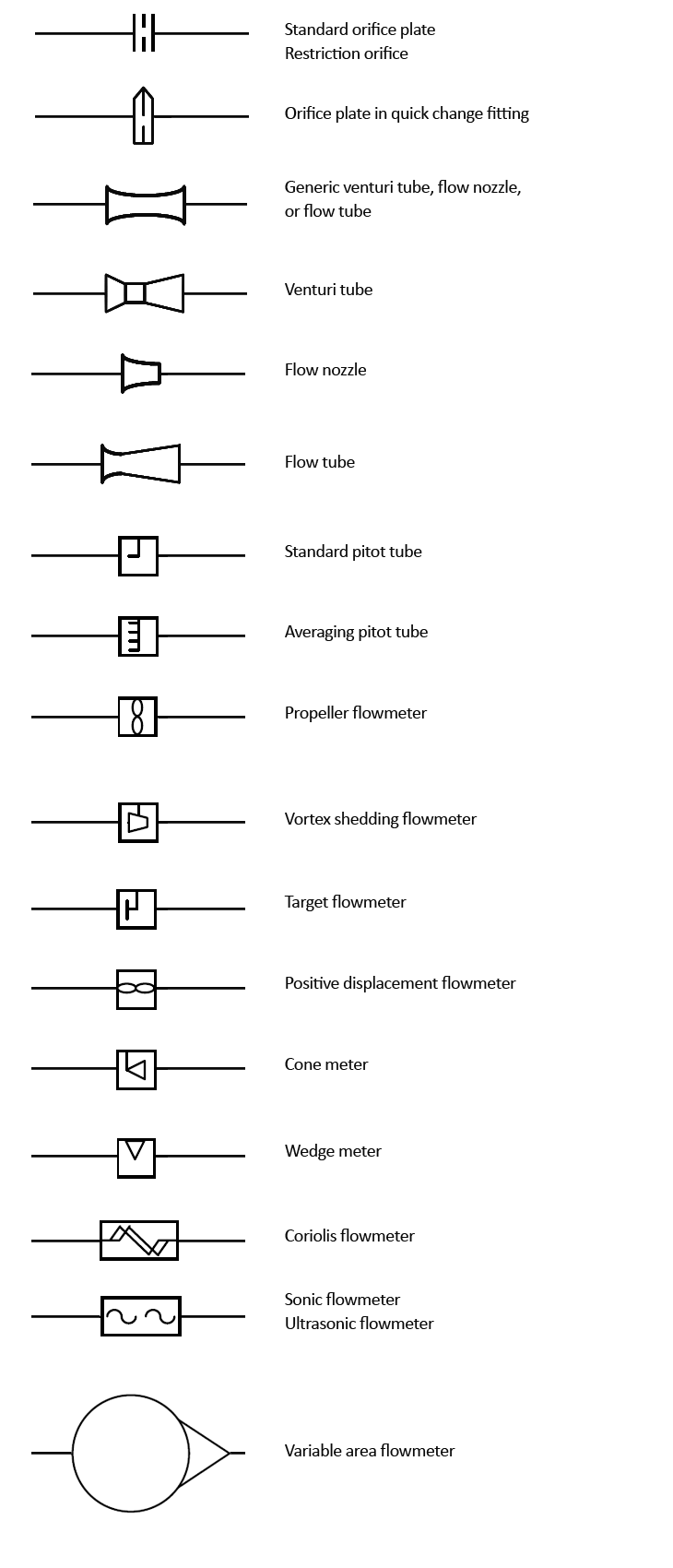
- primary elements
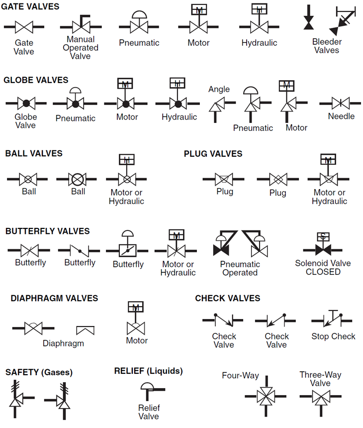
- valves
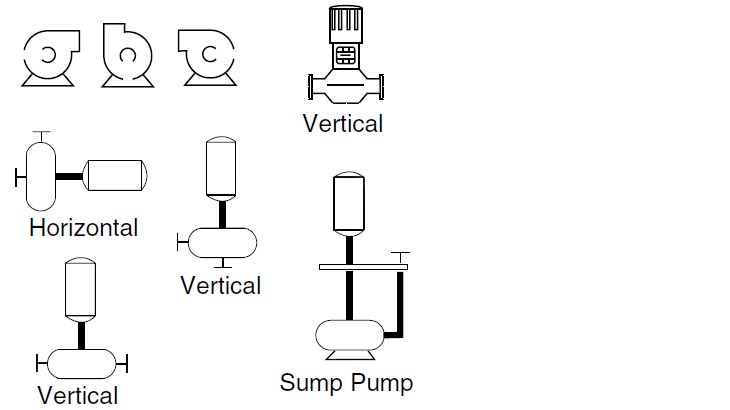
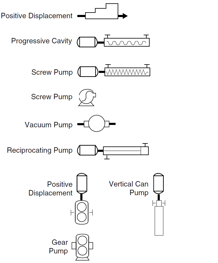
- pumps
- compressors
- vessels
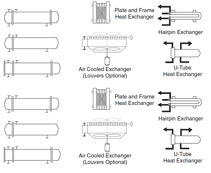
- heat exchangers
On Figure 1 is show a basic example of representing the physical equipment on the in the P&ID.
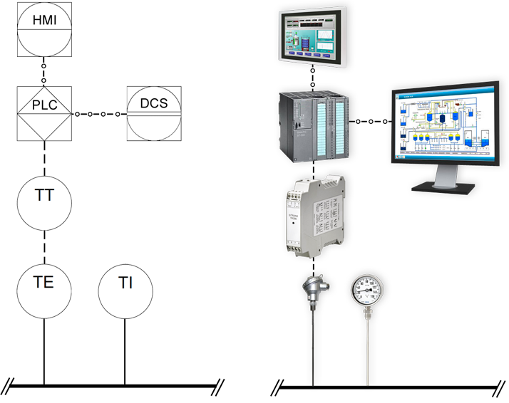
Figure 1.
General instrument or function symbols
Instrument Line symbols
Primary elements
Valves
Pumps
Centrifugal pumps
Positive displacement pumps
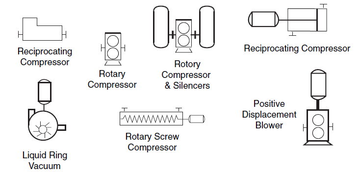
Compressors
Centrifugal compressors
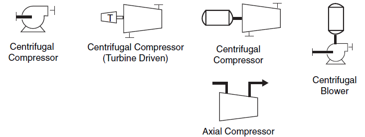
PD Compressors
Heat Exchangers
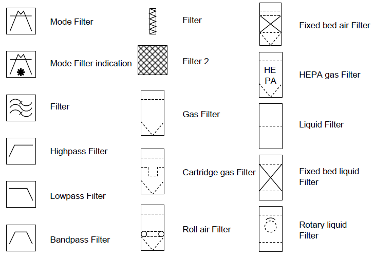
Filters
Related articles:
Process Flow Diagrams, Piping and Instrumentation Diagrams - basic definitions
Piping and Instrumentation Diagrams
TAG Numbers in process industry used to identify field devices according to ISA-5.1
0 COMMENTS //
Join the discussion