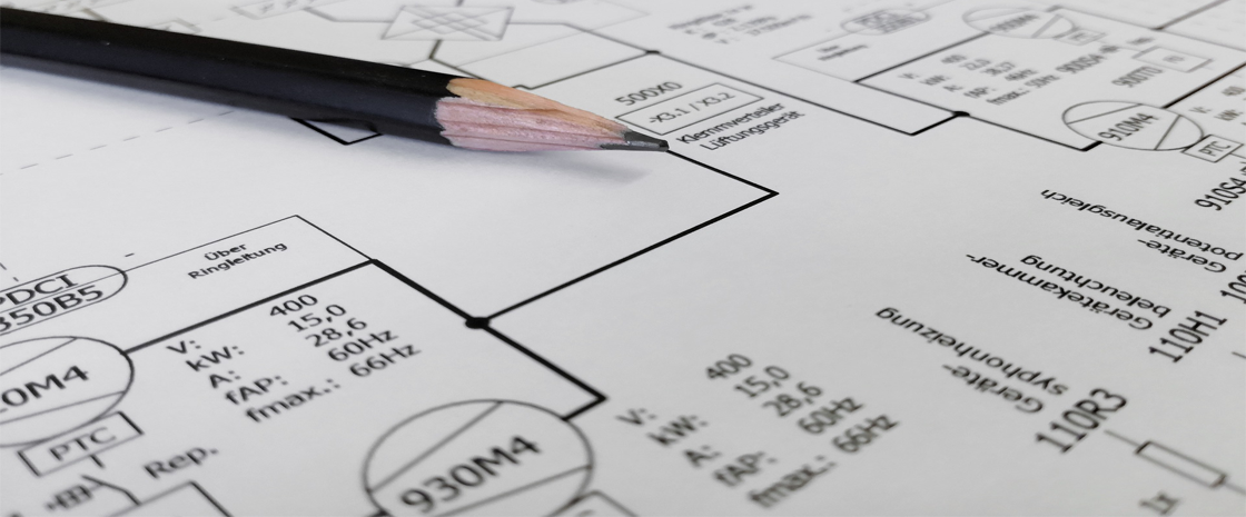
The Loop Diagrams extend the P&IDs, they show the components of the instrument loop, connections between devices and identification of component action, the specification of instrument hardware items and a means of communicating requirements.
Loop diagrams can be specified according to customer and project requirements. The most essential content of the loop diagrams shall include:
- Identification of the loop and loop components shown on the P&IDS.
- Word description of loop functions within the title. If not adequate, use a supplemental note. Identify any special features or functions of shutdown and safety circuits.
- Indication of the interrelation to other instrumentation loops, including overrides, interlocks, cascaded set points, shutdowns and safety circuits.
- All point-to-point interconnections with identifying numbers or colors of electrical cables, conductors, pneumatic multitubes, and individual pneumatic and hydraulic tubing. This identification of interconnections includes junction boxes, terminals, bulkheads, ports, and grounding connections.
- General location of devices such as field, panel, auxiliary equipment, rack, termination cabinet, cable spreading room, I/0 cabinet, etc.
- Energy sources of devices: electrical power, air supply, hydraulic fluid supply.
Voltage, pressure and other applicable requirements are to be identified. - Indication of what is being measured and what is being controlled.
- Actions or fail-safe positions (electronic, pneumatic or both) of control devices such as controllers, switches, control valves, solenoid valves, transmitters.
Additional information needs to be considered for its effectiveness in accommodating the intended uses. Stated below are typical examples of items for inclusion at the user's discretion.
- Process equipment, lines, and their identification numbers, source, designation, or flow direction.
- Reference to supplementary records and drawings, such as installation details, P&IDs, location drawings, wiring diagrams or drawings, and instrument specifications.
- Specific location of each device, such as elevation, area, panel subdivision, rack or cabinet number and location, I/O location, etc.
- References to equipment descriptions, manufacturers, model numbers, hardware types, specifications or data sheets, purchase order numbers, etc.
- Signal ranges and calibration information, including setpoint values for switches, and alarm and shutdown devices.
- Software reference numbers, such as I/O addresses, control block types and names, network interfaces, point names, etc.
- Engraving or legend information that helps identify the instrument or accessory.
- References to manufacturer's documentation such as schematics, connection details, operating instructions, etc.
- Color code identification for conductors or tubes that use numbers for differentiation.
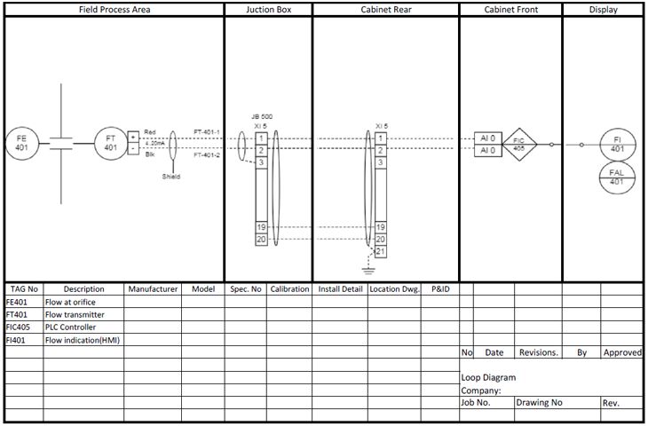
Figure 1. Instrument loop diagram
Combining the loop’s elements depends on the signal loop structure. The most common groups are:
Field process area
Field panel
Junction box
Cable spreading room
Cabinet
Cabinet rear
Cabinet front
Display / HMI
![]()
Identification of the Junction box Number – JB 500
Identification of the terminal number XI 5
FT 401 – Flow transmitter with wiring terminals.
The more informative and structured the loop diagram is, the easier it will be to commission and maintaining the system. For example: Loop diagram shows exactly what wire color to expect at exactly what point in an instrumentation system, and exactly what terminal that wire should connect to, it becomes much easier to proceed with any troubleshooting, calibration, or upgrade task.
References:
The International Society of Automation (ISA). www.isa.org.
0 COMMENTS //
Join the discussion