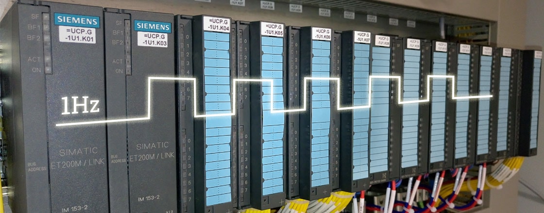
Most PLCs provide the possibility of configuring pulses like 1Hz, 2Hz etc. In the world of SIEMENS (TIA and the classic S7) we can do it using the PLC’s clock memory, by configuring the Memory Bytes in the Hardware configuration.
In the Hardware Configuration of the SIMATIC S7 Manager you can set Memory Byte number to be used, then it is going to be set as follows: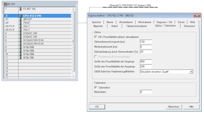
Figure 1. S7 PLC set up of memory byte for pulse generation in S7 Manager.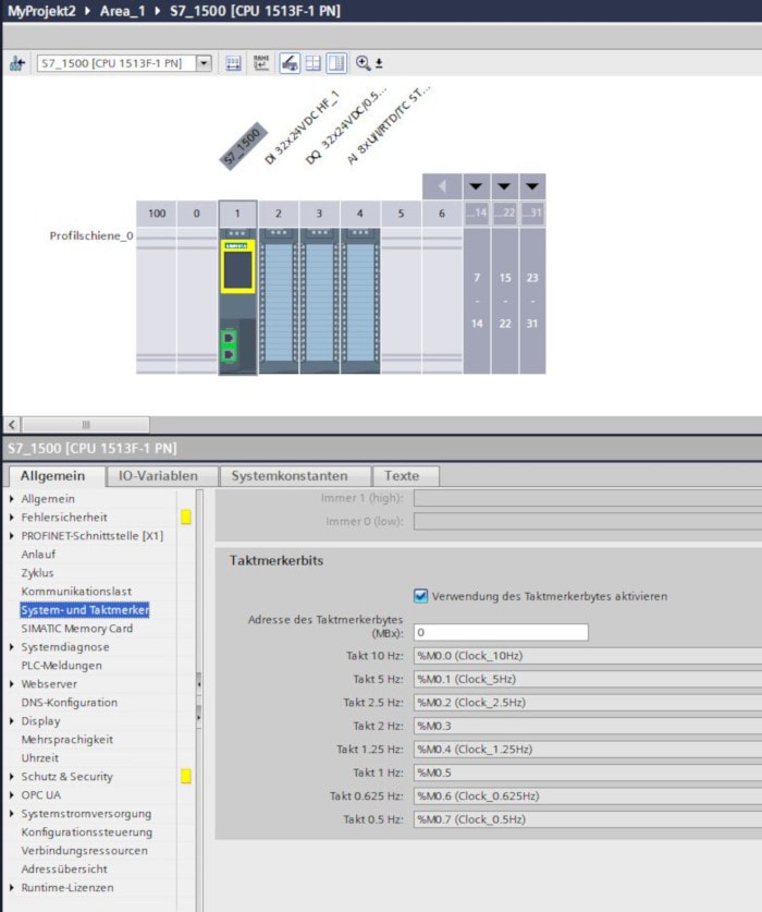
Figure 2. Set up of memory byte for pulse generation in TIA Portal.
|
Bit |
Period duration (s) |
Frequency (Hz) |
|---|---|---|
| 0 | 0.1 | 10 |
| 1 | 0.2 | 5 |
| 2 | 0.4 | 2.5 |
| 3 | 0.5 | 2 |
| 4 | 0.8 | 1.25 |
| 5 | 1 | 1 |
| 6 | 1.6 | 0.625 |
| 7 | 2 | 0.5 |
Table 1. Pulse period durations.
The hertz (Hz) is an unit derived from time which measures frequency in the International System of Units (SI). Frequency is how often something happens. A frequency of 1 hertz means that something happens once a second.
Sometimes we need some pulses with non-standard/freely chosen duration, for example ON-State duration 3s and OFF-State duration 1s.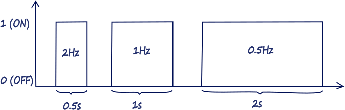
Figure 3. Pulses.
In the following demo code I will show a simple example of how to program pulses with different duration of the High (ON) and Low (OFF) states. The demo source codes are shown for Allen Bradley and SIEMENS PLCs, but they are applicable for any industrial controller which can be programmed according to IEC 61131-3.
Demo 1
The first demo is realised in Allen Bradley Studio 5000, Ladder Logic. I have used Two timers:
- TON – On delay timer.
- TOF – Off delay timer.
Timer parameters:
.EN – BOOL. The enable bit indicates the TON instruction is enabled.
.TT – BOOL. The timing bit indicates that a timing operation is in process
.DN – BOOL. The done bit indicates that .ACC ³ has reached .PRE.
.PRE – DINT. The preset value specifies the value (1 msec units) which the accumulated value must reach before the instruction sets the .DN bit.
.ACC – DINT. The accumulated value specifies the number of milliseconds that have elapsed since the TON instruction was enabled. When the TON instruction is disabled, the .ACC value is cleared.
The time base is always 1 msec. For example, for a 2 second timer, enter 2000 for the .PRE value.
The times have time base of one millisecond, so for the Preset parameter I’ve put the values 2000, this means the
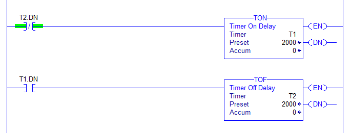
Figure 4. Pulse generator in Allen Bradley Studio 5000.
T2.DN can be used as the pulse state. The timers have time base of one millisecond, so for the Preset parameter I’ve put the values 2000, this means the ON and OFF states are last 2seconds each.
Demo 2
The second demo is realised in the classic SIMATIC TIA Portal in Function Block Diagram, the logic is the same as in Demo 1.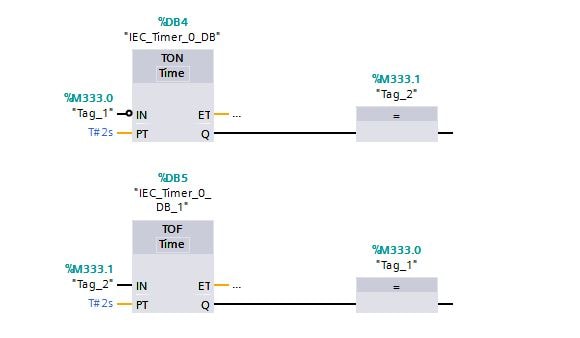
Figure . Pulse generator in SIEMENS TIA Portal.
Tag_1 in this case can be used for the pulse output.
TON delays a rising signal edge by the time PT. A rising edge at the IN input causes a rising edge at output Q after the time PT has expired. Q then remains set until the IN input changes to 0 again. If the IN input changes to 0 before the time PT has expired, output Q remains set to 0.
TOF delays a falling edge by the time PT. The timer runs only in the STARTUP and RUN modes. A rising edge at the IN input causes a rising edge at output Q. A falling edge at the IN input causes a falling edge at output Q delayed by the time PT.
0 COMMENTS //
Join the discussion