Energy management and optimizing energy consumption is crucial for modern plants and processes, variable frequency drives are being used in many general purpose applications where they are controlling electric motors. Using VFDs not only saves energy but also saves the life of motors by providing.
When using VFDs there are some considerations that need to be made when installing and commissioning the system.
One of the biggest considerations that need to be made is the power, control, ground, communication and analog control wiring techniques need to be understood fully to maintain proper operation, prolong the life of the system and reduce the EMI (Electromagnetic Interference).
Power Wiring
Sizing – The size of the power wires and fuses that are going to the VFD should be sized to handle the overall load and voltage rating of system. The wires going out the motor need to be sized based off the current and voltage that will be carried on them. In some applications this could be at a lower level depending on the motor load or if multiple motors are used the motor wiring should be sized for the load of all the individual motors.
Type – When looking at the type of cable to use it comes down to the insulation level it has to the prevent EMI. Single wire conductors can be used but shielded power cable is the preferred cable. This is the case for both input and output cables but with output cables instead of the interference radiating from the conductors, a larger shield will force the current noise back to the VFD’s bus. Specialty designed cables are made to handle VFD applications where four conductors are enclosed in a shielded cable, the voltage rating is typically higher in these cases due to the added insulation.
Routing – Routing is a major issue when looking at the input and output side of the drive. It is suggested that the input wires are kept apart from any output wires going to the motor. There is no standard spacing between power wires due to the type of cable that is selected and how it is shielded, but it is suggested that there be at least 3cm between cables if they have to run in parallel. If they have to cross each other it is suggested that they cross at a 90° angles to prevent interference.
Shielding – For the input and output motor leads it is suggested to have the shielding terminated on both ends to the ground location, to keep a common ground throughout the system. Running wiring in conduit will also provide some protection if a shield wire is not provided, but there could potentially be some noise induced from the contact points.
Control Wiring
Sizing – The sizing of the control wire is again going to be based off the current load and voltage that will be on them.
Type – When it comes to the type of cable to use, there are many options depending on the size requirements. Standard twisted pair cables will provide protection for EMI but it is suggested to use a shielded twisted pair cable. Some communication protocols have their own cabling standard that should be followed.
Routing – With the twisted pair cabling for control and communications they should not be routed by any high voltage (above 50VDC) power wiring. If they have to run parallel with high voltage wiring, they should be spaced apart as much as possible. A grounded barrier is preferred if possible between cables in parallel. If crossing over any high voltage cables it is suggested that it crosses at a 90° angle to prevent noise transmitting onto the signal wires.
Shielding – When having a shielded cable, it is suggest to ground the shield on one end of the cable, in most systems at the drive is preferred. There are ground straps that can be used to clamp around the cable shield to terminate. Do not terminate the ground through the pigtail connections or on the other end of the cable or it will increase the high frequency impedance and remove the effects of the shield.
Grounding
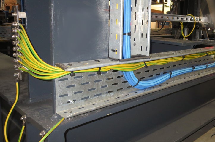
Grounding the equipment to the panel and system ground is the most important aspect to look at when trying to eliminate EMI issues and prevent high frequency currents from effecting other equipment throughout the power network. A specific ground connection should be made between the VFD and the motor with a direct point of contact. From there the VFD should be grounded to the facility ground along with any other devices that are in the cabinet or are used for controls. Painted back panel creates an insulation barrier between the Ground lug and grounding cable that can cause a bad ground connection.
Ground cables should be sized to the same size of the power wiring to again maintain the proper current level protection. Braided ground connections have lower high frequency impedance than round conductors and are preferred.
We view there a three level approach to a single drive installation, starting with the accepted standard.
It is a good practice to use shielded armor cabled or PVC jacketed shielded cable instead of conduit from the drive to the motor and shielded armored cable on the line and load side of the VFD.
The preferred method of using shielded or armored power cable is due the return path for common mode noise is the shield or armor. Unlike conduit, the shield or armor is isolated from accidental contact with grounds by a PVC outer coating. The coating makes the majority of noise current flow in the controlled path and very little high frequency noise flows into the ground grid. The armor prevents EMI coupling to other cables because the radiated emissions are minimal as the armor completely covers the power wires.
Communication Wiring
For communication wiring similar considerations should be made as the control wiring. Depending on the communication protocol used will determine in many cases the type of cable to use along with its connectors. The communication wiring should be separated from any high voltage wiring (above 50VDC) and if it should cross any high voltage wires (above 50VDC) at a 90° angle. When running parallel with any high voltage wires they should be spaced as far away as it is permitted to prevent any EMI interference.
Shielded Twisted pair cable is suggested with the shield terminated on one end will provide the best defense against EMI in in the system.
Analog Control Wiring
For analog control wiring similar considerations should be made as the control wiring. The analog control wiring should be separated from any high voltage wiring (above 50VDC) and if it should cross any high voltage wires (above 50VDC) at a 90° angle. When running parallel with any high voltage wires they should be spaced as far away as it is permitted to prevent any EMI interference. Shielded Twisted pair cable is suggested with the shield terminated on one end will provide the best defense against EMI in in the system.
EMC (Electromagnetic Compatibility) Zone concept inside the electric cabinet
The cabinet can be divided in EMC-Zones and mounting the devices should be accomplished according to the zones (Figure 1). The different zones should be electromagnetically separated. This separation can be done by placing the units in some distance from each other (about 25cm), nevertheless better and more practical concerning the space in the cabinet is separating by metal hoods or by isolating plates.
Wires from one zone can be traced without screens but the wires from the different zones should not be placed in same cable traces or cable loops.
On the connection between the different zones are to be placed filters or/and coupling modules. Coupling modules with galvanic isolation can reduce the disturbances between the different zones. All communication and signals wires going out of the cabinet should be shielded. If there are some signal lines with longer cable distances isolation amplifiers should be used. Between the zones should not be potential differences concerning the ground potential. For the cable shields should be enough surface to place on in order to assure gut contact with the cable ground.
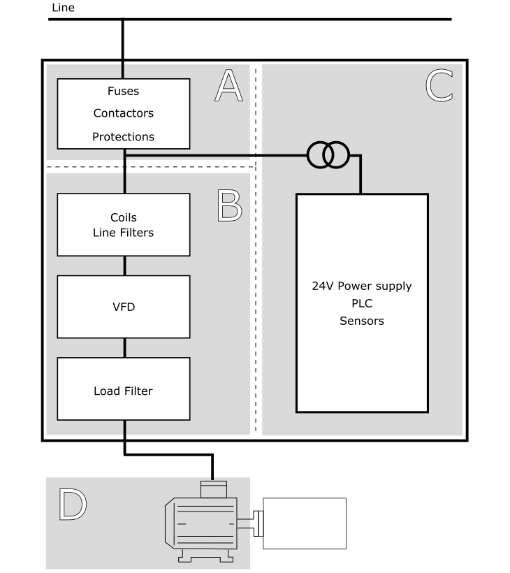
VFD Cabinet zones
Zone B: power electronics – source of noise
Zone C: Controlling and sensors
Zone D: Motors, Brake resistors, cables – source of noise
Related articles:
Variable Frequency Drives (VFD) Part 2 - commissioning

0 COMMENTS //
Join the discussion