The use of VFDs is very common nowadays, almost every plant or machine is equipped with electrical motors ran by FVDs. In reducing the commissioning time for your drives you reduce the allover time for the commissioning which leads to economic benefits for both investor and engineering company.
There are some basic steps which apply to the commissioning of every FVD. By fallowing these steps you can reduce the commissioning time and avoid misconfiguring of your drive.
1. Manufacturer data - first thing to do is get to know your drive, collect
information about the VFD provided from the manufacturer in form of user manuals (parameters, mounting procedure, commissioning procedure, troubleshooting). If trainings are provided from the manufacturer or distributer think about visiting them, some drives today come with more than thousand parameters a few days or ours of training can help maximizing efficiency.
2. If available use the configuration software tools. Some manufacturers deliver a setup software which is easy to handle and instead putting all parameters over the display it can be used to adjust the VFD.
3. Do as much as possible in the office, in this way eliminating distractions which occur on site is possible. Once you are on site the time is always short, some “hot topics” have priority and you receive every day new questions from the customer.
4. Commissioning the field devices. First make sure no mechanical problems are going to occur, consulting with the mechanical team is always helpful.
(these points also to be put in the check list)
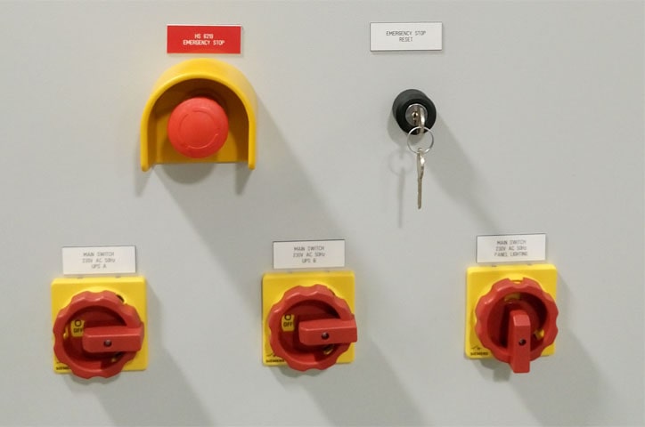
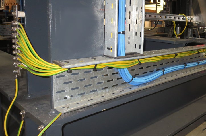
5. Check wirings to the VFD, to the motor and the signal exchange lines.
Make sure power and motor cables are correctly sized, installed and terminated.
All power cable shields have been correctly earthed at both ends. VFD should be grounded ton the power line side and at the motor side.
Control cables installed and all control cable shields have been correctly earthed at one end only, (preferably process control earth, ant the source end only). Also check the manufacturer’s recommendation on grounding and shielding.
Test motor cable isolation.
Possible wirings:
6. Collecting motor data. Before start configuring the parameters you should collect the motor data:
Note down the Article No. of the motor and the motor’s nameplate data. If available, note down the motor code on the motor’s nameplate.
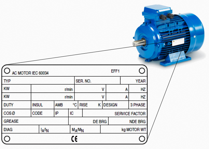
In which region of the world is the motor to be used, usually the input frequency is 50 or 60 Hz:
- Europe IEC: 50 Hz [kW]
- North America NEMA: 60 Hz [hp] or 60 Hz [kW]
How is the motor connected:
Pay attention to the connection of the motor (star connection [Y] or delta connection [Δ]). Some motors have on the inside of the wiring case a drawing which is showing the possible wirings. According to the art of wiring you have to read out the corresponding information from the name plate - for example if connected in delta than you have to use the delta connection parameters.

Note down also the motor voltage, motor current and power.
The number of AC power lines and the Power factor.
7. Setting the VFD parameters. After putting the nameplate parameters in the VFD you have finished the basic setting of your VFD, these are.
7.1. Current
7.2. Voltage
7.3. Motor power in kW (power of the shaft)
7.4. Frequency
7.5. Ramps
7.6. Hardwired signals
7.7. Motor control
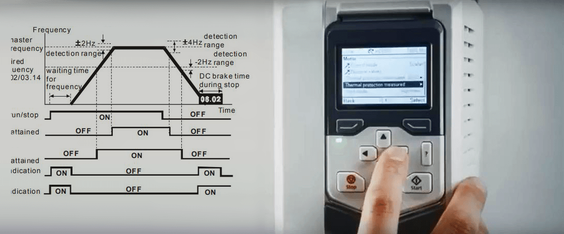
Frequency. There are some basic points to consider when setting the motor frequency.
Operation of the driven motor at less than 25% of the motor full speed rating may cause the motor to run with inadequate cooling. Inform the user that such operation may affect the motor life, and that he should verify with the motor manufacturer’s that the driven motor is rated for such operation.
If the driven motor is to operate at less than 50% of its name-plate speed, the thermal over-load protection may not properly protect the motor. The motor may overheat due to the reduction in ventilation at reduced speed even though it is operating at well less than its rated full load current. A thermally responsive overload protection device that responds to actual motor winding temperature may be required in this case.
For motors that are equipped with oil sleeve bearings, operation of the driven motor at less than 50% of the motor full speed rating may cause the bearings to receive inadequate lubrication. Inform the user that such operation may affect the motor life.
Some drives let you set Minimum and Max frequency.
This is how you can make sure that your motor would not rotate faster or slower than predefined. For example the VFD Set-point over Analog Input AI is 5mA and this corresponds to 20Hz, but the min frequency was limited over parameter to 30Hz, so the motor will run at minimum 30Hz.
Minimum speed is sometimes set above 0Hz to suit constant torque applications.
Ramps. The ramp-up and ramp-down times define the maximum motor acceleration when the speed set-point changes. Some VFD manufacturers recommend ramp times in accordance to the motor power
For example:
| kW | Appropriate ramp times |
|---|---|
| 0.37 - 3 kW | 30s |
| 4 - 15 kW | 60s |
| 18.5 - 30 kW | 90s |
| 37 - 90 kW | 120s |
Ramp UP and Ramp DOWN time
Inappropriate Ramp UP and Romp Down times may lead to malfunction of the VFDs or the motor.
If the ramp up time is selected too short it may cause overheating of the electrical motor. Ramp up time should be selected in relation to the inertia of the mechanical load and type of application. For example in a pumping application the acceleration time should be slow enough to prevent water hammer in the pipes (surging).
If the ramp down time is too short it may cause tripping of the VFD. Ramp down should be selected according to the inertia of the motor/mechanical equipment (the time to coast down). On high inertia loads this time should not be too short, if the deceleration time is below the natural rundown time of the load the DC voltage could rise to a high level and cause tripping on over voltage. Otherwise you have to use brake resistors. The deceleration time can be shorter if breaking resistor is used.
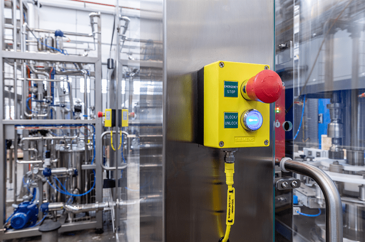
Digital and Analog I/Os.
Over the terminals you can control the VFD and use some of the outputs as feedback for the actual status of the drive.
Inputs - Start/Stop of the VFD, Speed Set-point or selecting the rotation direction.
Outputs - Actual speed, Fault or Alarm detection, Current.
Types of Motor control
There are two basic types of controlling the asynchronous motors.
The V/f or frequency control and the Vector control.
The most common control method is the V/f control, it is used for applications like: Pumps, Fans, Compressors, Transport bands.
The vector control method is complicated to be tuned but offers some advantages:
- More stable speed when change in the load occurs.
- Faster ramp up time when change in the set point occurs.
- Better protection for the motor and the mechanical equipment over settable Torque limitations.
- Full torque possible in stand still.
- Torque controlling possible in Vector mode.
Some typical applications are: Lifting equipment and vertical transporters; Winders; Extruders.
For some tuning specifics and features of these methods refer to the VFD’s user manual.
Additional parameters may be applicable like the motor cooling art:
Self cooling - with fan attached to the shaft
Cooler - fan cooler which is independent from the motor
Liquid cooling
No cooling
It is recommended that before connecting the cables to the motor first to put all correct parameters and before starting the motor for the first time to dismount the mechanical equipment and check rotation directions, response of the motor to changes in the set point (frequency).
Related articles:
Variable Frequency Drives (VFD) Part 1 - Wiring
0 COMMENTS //
Join the discussion