A simple setup for simulating 4..20mA signal to a PLC Analog inputs can be done by using a linear potentiometer
For testing and calibrating current loops there is a variety of distributors (for example FLUKE) which offer professional tools, with such equipment you can check, measure or calibrate your current loops. But if you just want to simulate 4..20mA signal and simply test some functionality of your PLC, then there is a simple and cheap solution to do it.
So, what do you need?
1 x Linear (Lin) potentiometer 4K7 Ohm.
With linear potentiometers, the resistance between one end of the track and the position of shaft rotation (or swipe) varies at a constant rate as the shaft (slider) is prepositioned.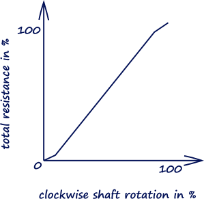
Figure 1. Characteristic of linear potentiometer.
1 x resistance 1K2 Ohm.
Some wires and knowing the Ohm’s wall.
More about current loops you can find here “4..20mA Current Loops”. In fact, the whole philosophy is very simple, these loops are based on Ohm’s Law: V = I x R. The voltage (V) is equal to the current (I) multiplied by the resistance (R).
Ohm’s law I=U/R George Simon Ohm (1787 – 1854) was a German physics who in 1826 discovered that there is a direct proportionality between the potential difference (voltage) applied across a conductor and the resultant electric current. This relationship is known as Ohm's law.
A simple calculation here will give us the ranges:
Minimum current: 24/(4700+1200) = 0,004 A => 4 mA
Maximum current: 24/(1200) = 0,02 A => 20,0 mA.
To simulate the 4..20mA signal we must connect the linear potentiometer in series with the resistance, and adjust the PLC analog module for 2Wire.
To make sure the loop is functioning I will suggest connecting a multimeter in series between R2 and the “-” side of the PLC channel. Alternate to R2 (1K2 Ohm) is using a 470 Ohm resistance (some PLCs have integrated 250 Ohm shunt resistor).
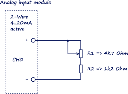
Figure 2. Connecting the potentiometer for 2-Wire measurement.
If you want to simulate the case with 4 Wire measurement and passive Analog input the you also need:
1 x resistance 6K8 Ohm.
1 x 24VDC Power supply.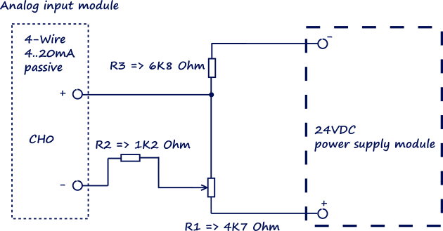
Figure 3. Connecting the potentiometer for 4-Wire measurement.
These were two simple examples for simulating a 4..20mA signal. You if need a stable and calibrated signal, then I suggest spending some money on professional equipment.
Related articles
4..20 mA Current loops
4..20 mA Current loops: 2, 3 and 4 Wire transmitters
0 COMMENTS //
Join the discussion