Variable frequency drive (VFD) are used to protect AC motors and to control their speed by varying the frequency and voltage supplied to the electric motor.
Ho do VFDs work
VFDs convert input power to adjustable frequency and voltage source for controlling speed of AC induction motors. The frequency of the power applied to an AC motor determines the motor speed. The Speed of the Motor is directly proportional to the Frequency (f) because the number of motor poles is fixed, so the motor speed can be controlled by varying the system frequency.
N = 120 x f / p
N = speed (rpm)
f = frequency (Hz)
p = number of motor poles
Example: N = 120 x 50 / 4
N = 1500 (rpm)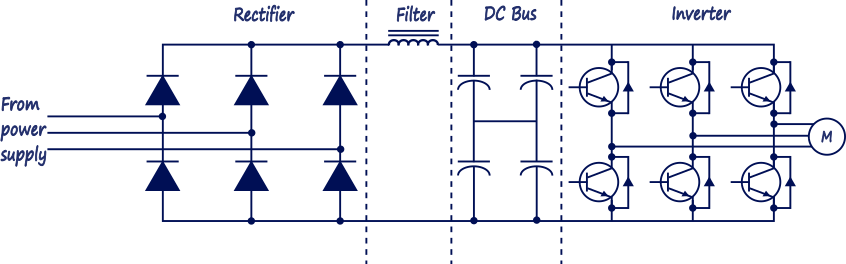
Figure 1. Scheme of VFD.
The first module of a Variable Frequency AC Drive is the Rectifier (Converter). It consists of six diodes. They allow current to flow in only one direction; the direction shown by the arrow in the diode symbol. The principle of the variable frequency drive three phase half-wave rectification is capturing the positive or negative peaks of the three phase voltages by means of three diodes. Different designs are available and these are selected according to the performance required of the variable frequency drive.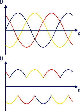
Figure 2. Rectifier. Capturing of positive and negative peaks.
Intermediate circuit. Filter and DC Bus: the rectified DC supply is then conditioned in the intermediate circuit, normally by a combination of inductors and capacitors. By adding capacitors, smooth DC voltage is delivered.
The Inverter uses DC power from the DC bus and filter to invert an output that resembles sine wave AC power using a pulse width modulation (PWM) technique. Pulse width modulation uses transistors which switch the DC voltage on and off in a defined sequence to produce the AC output voltage and frequency. The transistors act as a switch connecting the DC bus across the windings of the motor. When we close one of the top switches in the inverter, that phase of the motor is connected to the positive dc bus and the voltage on that phase becomes positive. When we close one of the bottom switches in the converter, that phase is connected to the negative dc bus and becomes negative. Thus, we can make any phase on the motor become positive or negative at will and can thus generate any frequency that we want.
The switching frequency refers to the rate of the on/off switching if the individual transistors. A higher switching rate will provide a cleaner waveform to the motor as there will be more pulses over each half wave. In addition to the motor torque (current), the motor speed (frequency) can also be controlled by utilizing PWM. By changing the period of the voltage pulses which induce the current in the motor phases the resulting output current waveform frequency can be changed.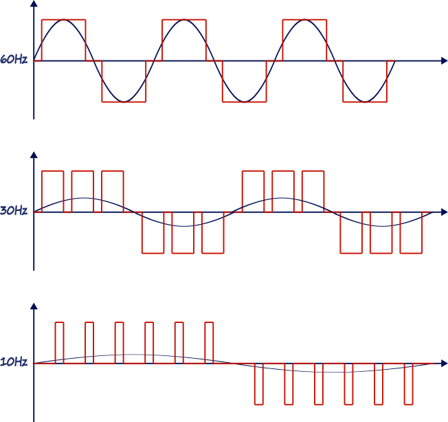
Figure 3. Pulse width modulation (PWM).
Usage
VFDs can be used in application where:
- custom motor control is needed.
- energy needs to be saved.
- speed control is needed.
One of the greatest benefits of VFDs is the energy saving, the most common usage of VFDs is in applications for transport belts, pumps, fans and compressors.
Related articles:
Variable Frequency Drives (VFD) Part 1 - Wiring
Variable Frequency Drives (VFD) Part 2 - Commissioning
VFD Troubleshooting and preventive maintenance

1 COMMENT //
Join the discussion
JANEMING 09 Sep 2021
nice information